Homemade Ballast
The first homemade ballast.
When this was used with my PDT this ballast was starting to saturate, as it was originally designed to work with my lower current Homemade Transformer.
I therefore decided to construct the variable ballast shown below.
For the PDT ballast I utilised the transformer from an old welder. With the welder's secondary short-circuited it gave me a variable range of inductance across its primary winding of 20m/H, up to 60 m/H.
When this is placed in series with the input of the pole distribution transformer (PDT) this gives an equivalent PDT secondary side inductance of 43H to 129H
This increased value comes about because any inductance on the primary side is 'seen' by the secondary side of a transformer. In doing so the value of the inductance on the primary side is multiplied by the transformer's turn ratio ^2 (squared).
(turns ratio = 46.2. So 20mH will become 46.2*46.2*0.02 = 42.69H)
Conversely a secondary inductance would appear smaller to the primary side and will equal the secondary side value divided by the turns ratio ^2.
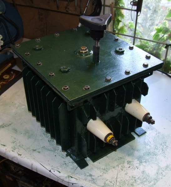
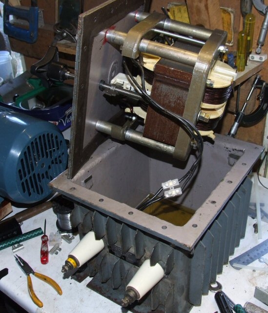
This case originally housed a 5H 2500v HV inductor and was oil filled. By turning the welder's core through 90 degrees so that the adjustment handle and its shaft emerged out of the top, it made an ideal choice for my variable ballast. The case is once again oil filled allowing the entire core to be under oil to assist with cooling.
The ability to vary the inductance comes about because of a sliding lamination between the primary and secondary coils. This slide is attached to the threaded rod that projects out of the top of the case.
A Replacement Ballast
As my power demands increased I found that the variable ballast also proved to be unsatisfactory, as the core was not really up to handling 6kW or more without overheating, despite the fact it was submerged in oil.
I had found that a 3 minute continuous run could cause the exterior of the case to feel quite warm, indicating the actual windings were considerably hotter.
(Later inspection showed signs of burning)
Another problem was that the undersized windings gave a resistance of 1.1 ohms, which with a current of 30 amps would mean a voltage drop of around 33 volts, this then becoming a 1500 volt drop on the secondary side of the transformer!
I therefore decided to build a heavy duty ballast and for this I chose to have a central core size of 12 sq inches. As the ballast would also have an air gap that would be packed with plastic, then there shouldn't be any chance of it saturating with my proposed 7.0 to 7.5kW load.
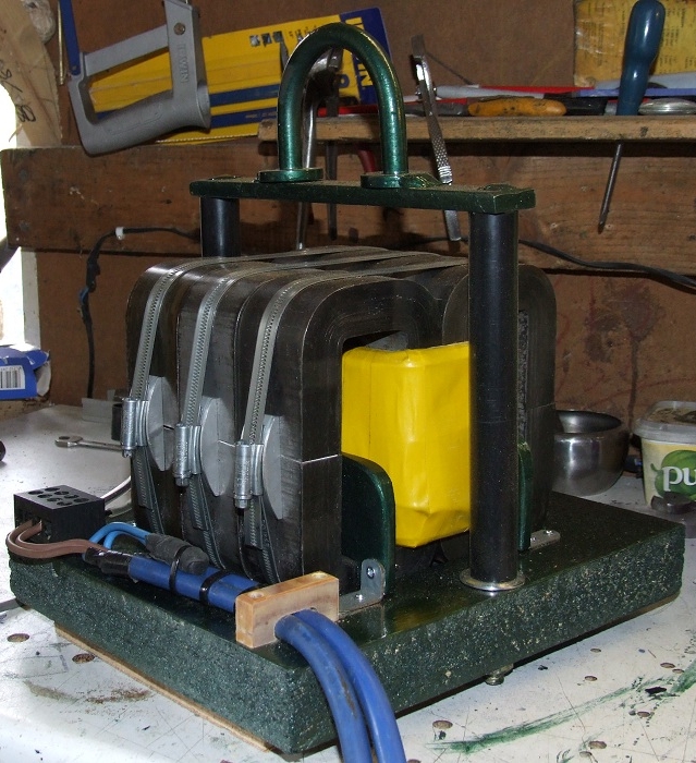
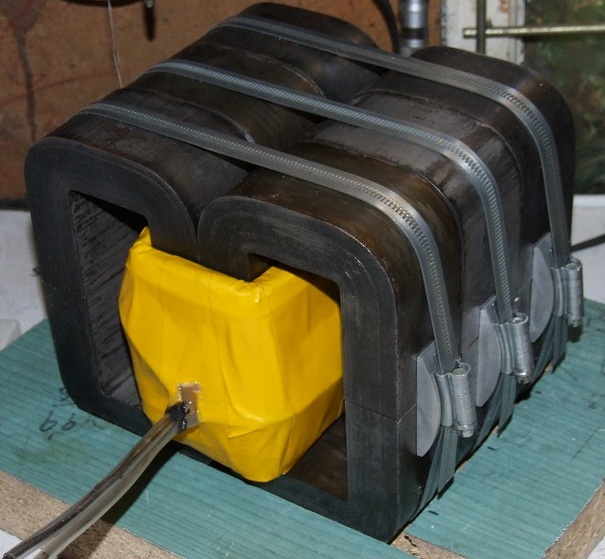
Above: The Finished Ballast
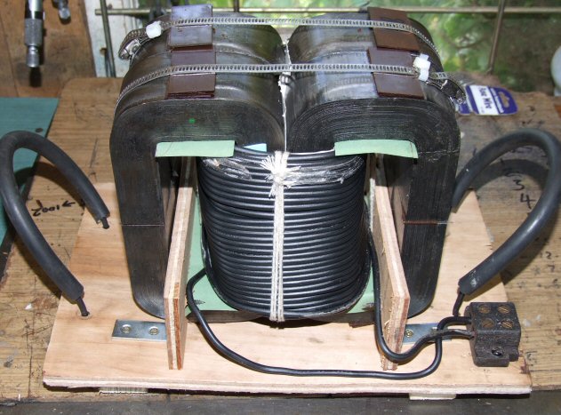
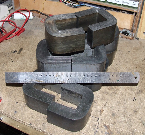
Left: The bare cores
Each pair of cores when joined measure approx' 6.5 x 3.8 inches by 2 inches deep.
I carried out some tests using old wire, and I found that just 35 turns of 1.6mm would give 18mH around a 12 sq inch core.
This shows that the permeability of the cores is fairly high, which comes as no surprise as they were from a radar transformer and matching ballast (the case of which I used for the variable inductor), and consequently built to a high specification.
For the actual ballast winding, I will be using thicker 3mm wire (AWG 9) instead of the 1.6mm used for the test.
The basic construction using six pairs of 'U' cores.
Each pair has a surface area of 4 sq inches in the central section, giving a total of 12 sq inches for the three. Total number of cores used for the top and bottom is twelve - so it will be heavy (30 pounds+).
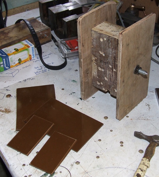
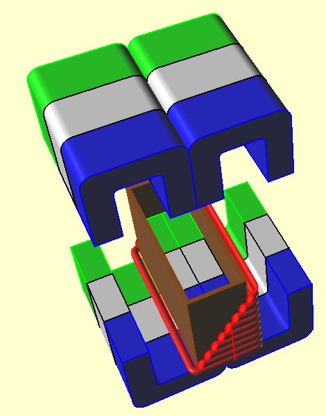
The central wooden area of the former is the same size as the central area of the cores. The Tufnol 0.125 inch thick boards were placed around the central wooden core and then had the magnet wire wrapped around. (see diagram above).
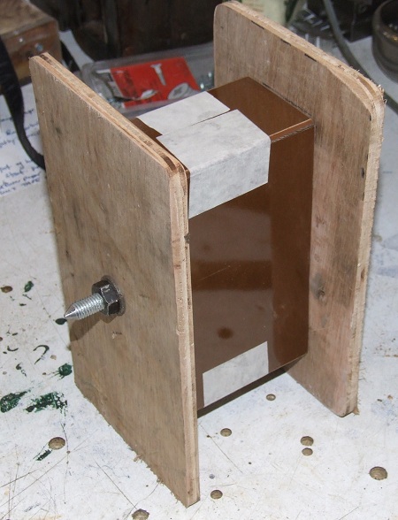
Once the coil is wound around the Tufnol boards, the two wooden side sections are removed and the whole coil, including the Tufnol boards, are all slid off the central wooden former and placed in position over the cores.
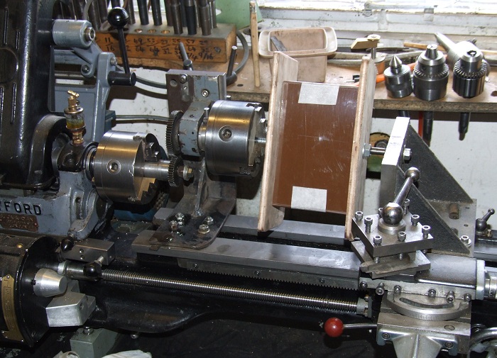
My lathe centre height was not sufficient as standard, so some improvisation was needed.
This was achieved by the lathe's own chuck driving an auxiliary one which is raised up above the bed. I have successfully used this method in the past to wind both a six inch and my present eight inch tesla coil secondaries.
I found the 3mm AWG 9 wire to be very stiff to wind around the wooden former, and I was in fact tensioning the wire by gripping it with both hands and hanging backwards as the lathe pulled against me. For this reason you need a very solid set-up for the winding jig. I doubt a homemade coil winder that is free standing would cope with the forces unless it is bolted to something solid, so bear this in mind if you decide to wind something similar. Also try to make the wooden former from a solid wooden block, making sure that is well supported at its far end by a tail stock or something similar.
The use of the back gear on the lathe, combined with the variable frequency drive, allowed me a winding speed of 4 rpm. This may seem slow, but with that gauge of wire it was definitely needed.
Winding on the lathe.
This was done using the lathe set up shown above.
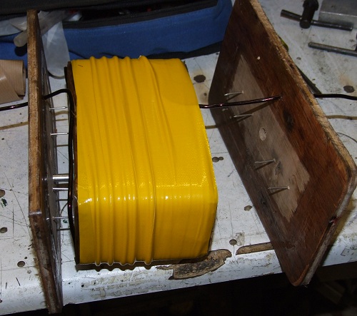
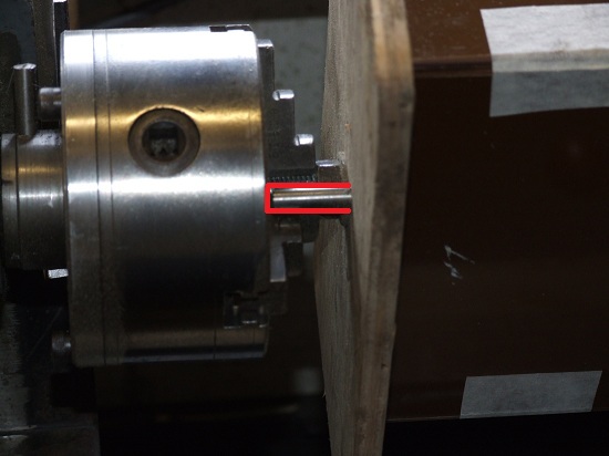
Once the winding was completed the side pieces were removed.
The two side pieces were held in place by the threaded studding that passed through the wooden former's centre and that the chuck was gripping on. This clamped the two sides to the central block together. The force of bending the thick wire would have easily pushed the sides outwards otherwise.
The nails you can see were just to stop the sides twisting on their axis, while the short metal stud on the left hand side, is the steel peg that bore against the chuck's jaw.
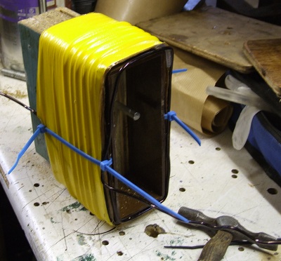
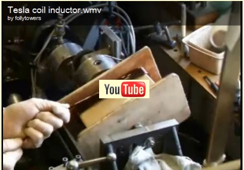
The wooden former is driven out.
The surface of the former had previously been smeared with grease to allow the Tufnol sheets to slide off easily.
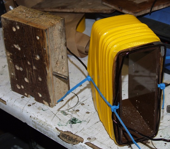
The cable straps are just temporary to stop the lower windings from slipping off the Tufnol former.
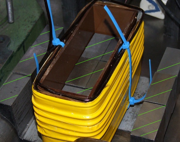
The plastic shims will be placed on the faces where the respective halves of each core meet (green hatching).
Once shimmed with 35 thou of plastic, I obtained 18.5mH from 64 turns of AWG 9 (3mm) wire.
Prior to the shimming I initially had 55mH from the 64 turns, when it was fully assembled.