Resonant Charging
(Copyright of this article: Richie Burnett )
I have included his TCML post here for convenience as it allows me to also included the two graphs he refers to.
(The links given in the original posting now being dead).
Over to Richie......
Hi guys, About a week ago, I said that I would go through my method for designing the AC resonant charging circuit for a tesla coil.
What I am going to explain is a way in which I propose that the ballast and tank capacitor values for a particular system can be determined at the design stage. i.e. You choose the rotary speed, and how many kW of power you want, and use the following steps to obtain the required ballast inductance and tank capacitance.As a bonus this method also achieves good power factor.
I should say that this is very much "simulation based" at this stage, as I haven't built lots of different systems to prove every combination. However, I have used Microsim extensively to verify my work, and have got promising results.What little practical work I have been able to do has also closely matched the predicted performance.
Ok, here goes......
Let's say I want to design a Tesla Coil to process 10 kW of real power, using a 12 kV power transformer, and a 371 BPS asynchronous rotary gap.Power feed is from 250V at 50Hz, and at this stage I have no idea what ballast inductance or tank capacitor value would give good results.
One possible approach would be to try many combinations of ballasts and capacitors in simulations until the combination that results in best performance is found. This is what I did and it was _VERY_ time consuming ! I did this so hopefully you don't have to take this hit and miss approach.
STEP 1: Determine what the resonant frequency of the charging
circuit should be for your chosen rotary firing rate (BPS.)
We know that the ballast inductor at the primary side of the power transformer resonates with the tank capacitor at the secondary. There have been many references to LTR caps. We are not concerned with whether the cap is larger or smaller than a particular value. We are only concerned with what the actual resonant frequency of the charging circuit is. In this design approach there is nothing special about resonance at 50 or 60 Hz.
For a whole range of break rates, I tried simulating charging circuits with different resonant frequencies. Particular attention was paid to the charging waveforms and power factor. As I explained before, it is the resonant frequency of the charging circuit which determines all of the timing related stuff like how quickly the cap charges between firings, and the power factor. So the resonant frequency should be made right to start with.
The graph here.....
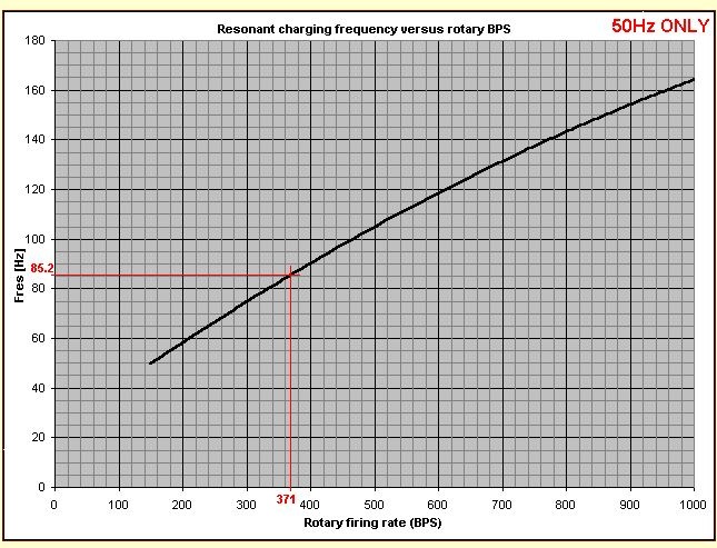
.....displays what I (Richie) think the resonant frequency of the charging circuit should be for different rotary break rates to get a power factor of 0.85
In our example the rotary break rate is 371BPS so the charging circuit should be designed to resonate at 85.2 Hz.
That ensures a PF of 0.85 at 371BPS, and ties down the product of the ballast and the tank capacitor, but there are still many combinations that would give the same resonant frequency. Indeed all combinations which give the correct resonant frequency do give the same charging waveforms and good power factor ! As long as the product of L and C is right for the chosen BPS, the resonant frequency is right and the charging circuit works correctly.
Choosing various combinations of L and C only changes one thing.
The * POWER THROUGHPUT *.
STEP 2: Determine what the ballast inductance should be.
If changing the ballast and tank cap values together only alters the power throughput, then we can adjust these values to get whatever power level we want. However if we don't know where to start, how can we pick a value for one of them without guessing and trying something first ?
Well, a good place to start is by ballasting the transformer to whatever power throughput we desire. In our example, the desired power throughput is 10kW, so we need to work out what ballast inductance will limit the transformer to 10kVA when its secondary winding is shorted.
10kW represents a current of 40 Amps at 250 Volts. Therefore the ballast choke should present an impedance of 6.25 Ohms. At our supply frequency of 50Hz, that requires 19.9 mH of inductance.
This figure of 19.9mH for the ballast is a "first-approximation". Although it draws 10kVA when the transformer is short-circuited, it is unlikely that this will give exactly 10kW of real power throughput at our chosen break rate. Life is just not that easy ;-)
STEP 3: Adjust the ballast inductance depending on chosen break rate.
If we used the ballast value calculated above, the real power throughput would be somewhat less than our desired 10kW. The actual shortfall depends on the rotary break rate.
The graph here...
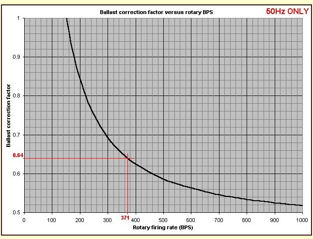
......shows what the real power output is as a fraction of the "ballasted VA" for different rotary speeds. Notice that low speeds give almost the full "ballasted VA" as real power, but higher speeds give progressively less real power for the same ballast setting.
For our chosen rotary speed of 371 BPS, it can be seen that the running Tesla Coil would process only 64% of the 10kVA that it was ballasted to draw with a short-circuit. Therefore we must multiply the ballast inductance by 0.64 to correct for this shortfall and meet the desired power throughput criteria.
0.64 x 19.9mH = 12.74 mH
The "corrected" ballast inductance is 12.74mH, and this is the value that we must use to get our full 10kW of power throughput when running.
STEP 4: Calculate the required tank capacitor value.
Now that we know the ballast inductance, and the resonant frequency of the charging circuit, we can finally calculate what the tank capacitance should be.
First we need to imagine that the ballast inductor is at the high- voltage side of the power transformer, instead of at the low voltage primary side. This enables us to deal with the ballast inductor and tank capacitor like a series resonant circuit. The equation:
F = 1 / [ 2 pi sqrt (L x C) ] can then be used as normal.
In our example the power transformer steps 250 Volts up to 12000 Volts, so it has a turns ratio of 48. Impedances are transformed by the square of the turns ratio, so our 12.74 mH ballast inductor becomes 48 x 48 x 0.01274 = 29.35 H when referred to the secondary side.
Re-arranging our resonant frequency equation and plugging-in the values for F (85.2) and L (29.35) gives us a tank capacitance of 119 nF. And that is it.
To summarise the ballast is 12.74 mH and the tank capacitor is 119nF.
This gives us a system that processes 10kW of real power at 0.85 PF
with our 12kV transformer and 371 BPS rotary spark gap. (Running a
Microsim simulation with these parameters gave me 10080 W of power,
11999 VA, and therefore a PF is 0.84)
There are two useful advantages of knowing that the approximate power factor is 0.85:
1. We can estimate the VA or current draw from the 250 Volt supply. In this case the real power is 10kW, so the VA = 10000 / 0.85 The VA = 11.76 kVA, or 47 Amps from our 250 Volt supply.
2. We can calculate the optimum PFC capacitance to improve PF further. With a PF of 0.85, the VARs are roughly equal to _half_ the watts. Therefore we need 5kVAr of PFC correction capacitance across the supply to achieve the absolute maximum power factor. That is a capacitive current of 20 Amps at 250 volts requiring 255uF of capacitance at 50Hz. This will cancel any remaining reactive current and maximise power factor.
Increasing or decreasing the power:
Remember that all the timing type behaviour is determined by the resonant frequency. If you want to double the power throughput of your design, all you need to do is double the tank capacitance and halve the ballast inductance. (Assuming the power transformer can cope ;-)
This will process twice the power due to the reduction in impedance. However, the charging waveforms, peak voltages, and power factor are not changed because the resonant frequency of the charging circuit has not changed !
There is nothing particularly special about the design method described here. All I have done is run a large number of simulations to find out what works best at various break rates. Then I have condensed this data into two graphs showing:
1. What the resonant charging frequency should be for various BPS.
2. How much the ballast needs to be adjusted to get the desired power.
Now you can work backwards from Watts and BPS to get ballast inductance and tank capacitance reasonably easily. Think of this method as being like a lookup table.
Congratulation if you have read this far, I appreciate that this stuff is heavy going !!! This kind of approximations and calculations are ideally suited to a computer program, so I intend to produce a simple program to do all this stuff automatically. It will ask for your intended power level in kW and your rotary speed in BPS. It will then calculate the suggested ballast and capacitor values as explained above, but much faster than using graphs and a calculator.
I hope that the above information is error free, and has provided some insight into the work that I have been doing for some time. If you have any questions, criticisms or suggestions I will try to deal with them as quickly as possible.
Regardless of whether you understand the method or you just use the computer program, I hope this work will lead to bigger sparks for all ;-)