Rebuild of 8 Inch Tesla Coil (2)
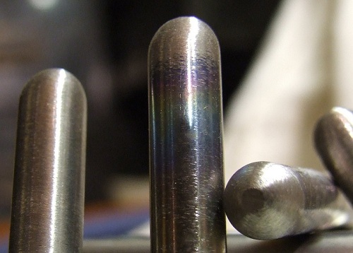
Provided I grind these to be exactly the same length (2.8" +/- 0.001"), it means that despite any run-out on the rotor (in my case 0.002"), with careful lateral positioning of the electrode within their holders, I can run the gap with a minimal clearance each side - typically about 0.008".
I have found that with a SRSG it can be harder to get the correct phase setting on a large (>0.018") gap.
The ends of the electrodes were rounded, as is my normal practice, to avoid any sharp edges which can cause overheating. I have however left the centres of each end flat to help with setting the gap.
It has to be remembered in a correctly setup tesla coil, that by the time the electrode have truly aligned, the capacitor has fired anyway, and the tank oscillations have all but finished.
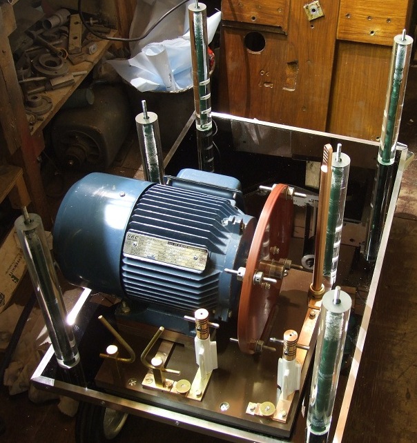
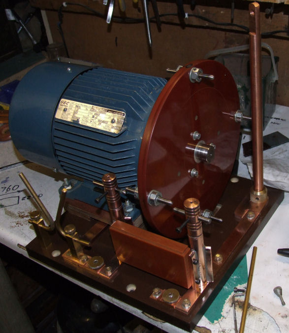
The SRSG on its new base.
The Tufnol base of the SRSG sits on a rubber mat which in turn sits on a sheet of 3mm black Acrylic.
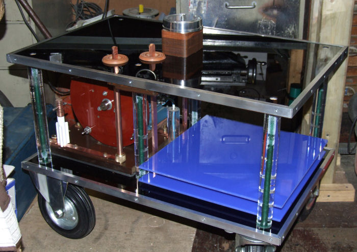
The MMC Trays
The four blue MMC trays will each have just two short leads connecting to the two vertical rectangular copper busbars.
These can just be seen at the tray's rear (middle area of the lower shelf). This arrangement should make removing a tray for maintenance a fairly straight forward affair.
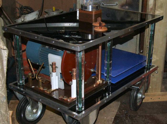
The whole affair is quite compact, but will dismantle quite easily when needed.
The partly built four MMC trays The sheets of blue acrylic had nine shallow channels cut into them with a router. This located the caps nicely, but had the problem of causing the acrylic sheets to bow slightly, because of the removed material. This was overcome by gluing reinforcing strips on their underside.
Next a total of 432 holes had to be drilled in the trays for the cable straps, and although a template was used, this still proved rather tedious to do.
Each tray consists of 54 capacitors comprising of 3 strings of 18 in series. This gives a voltage rating of 36K and a total capacitance of 0.1uF or 100nF for the whole MMC.
(Update Feb 2013: Another tray was added making 5 trays in all for 125 nF. Total number of caps = 270)
Once completed I felt the trays should have been made larger however, as although this arrangement looks tidy, it means the capacitors have fairly short tails to them. Also as the connections involve twisting before soldering, it makes future replacement difficult.
Merely just arranging the capacitors leads side-by-side and soldering without mechanically twisting them, could create an extra resistance, as solder only has around 20% the conductivity of copper. While only a very small resistance point, power lost is I^2*R, and the MMC does pass fairly high current pulses through its 270 solder connections.
Capacitances of this size should really be using dedicated pulse caps, like Maxwells for example. This would overcome these problems and also reduce the amount of construction and most likely costs as well, if the Maxwells were purchased secondhand.
One of the four trays from the MMC with the wiring now in place.
Each tray of caps just slides into place and the two connections (circled yellow) then connect to their respective copper busbar by bolts. The heavy wiring is in excess of what is needed in places, but much like my use of over-size copper bars in the SRSG below, it will serve no harm.
Update: 25th April 2011
Additional strips (arrowed in red) were later inserted to stop flash-overs that might occur between adjacent strings. This of course makes capacitor removal even more difficult than it was previously! But if proper allowance had been made at the outset, then this method should be very robust against flash-overs.
The soldered and twisted tails of each capacitor (arrowed in yellow) have had a dab of hot glue applied and then a short piece of plastic tube slid on to insulate the ends.
Finished SRSG - Two Steps Forward, One Step Back
I was never happy with the new electrode's mounting arrangement, as it was possible for the two terminal posts to twist on their mounting (a single bolt from underneath screws up into their base) allowing the stationary and rotary electrodes to crash together. (The original arrangement is shown Here)I prefer to run with a 10 thou gap to cut down losses, so the primary was designed, against modern doctrine, not to have excessive turns. Modern multi-gap spark gaps need higher primary turns to keep the current down, but a RSG running close tolerances has lower losses.
Therefore to stop any possible twisting I introduced a Tufnol bracing piece between the electrode posts, and secure it to the posts by four small bolts. This makes the whole affair very rigid, and hopefully I can now run with a small gap.
Update 2013: The Tufnol flashed over, as did the base as well. See Rebuild Page
Originally I had run out of copper bar so had used two pieces of brass, but a recent find amongst my junk allowed me to replace these two brass sections as well. This now means the entire tank circuit is made from copper bar or rod. The size of the rod and bars is far larger than is needed, but it will not in any way be detrimental.