Building a Tesla Coil
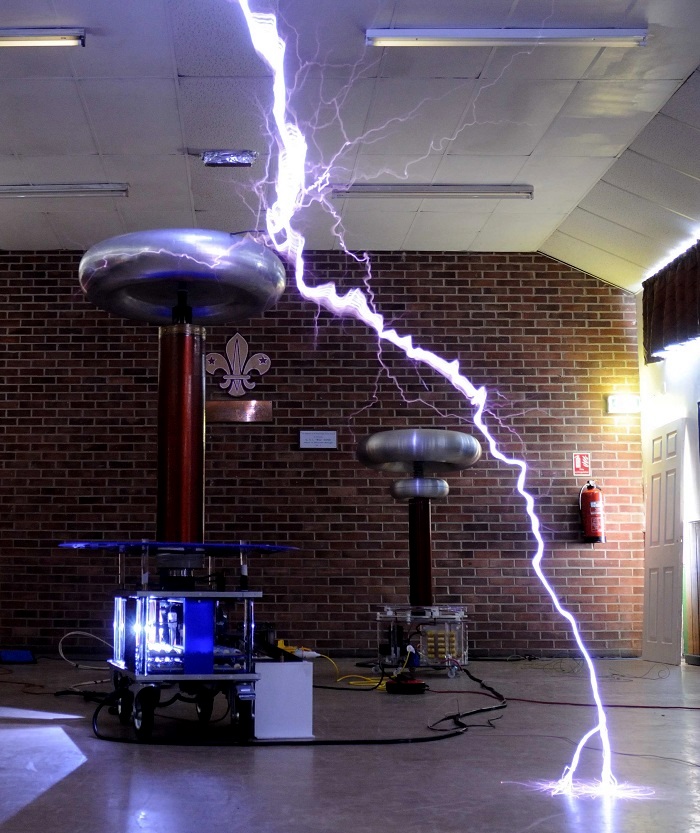
Running at Nottingham 2013
My 8 inch SRSG Phoenix coil in action, while the coil at the rear belongs to P Strauss (that has some astonishing performance for a 6 inch coil running on just a static gap).The white box to the right hand side of my coil on the floor, is a 62nF pulse cap belonging to Mr Strauss. This boosted my capacitance to 115nF at that time.
As of 2015 the coil now runs 125nF and has a lower value Ballast for more power. Also I have the use of a larger Toroid, all resulting in increased performance (see on the Videos page).
Skip the introduction below
and go straight to the
Design Example
using JAVATC
(Page 1 of 2)
As tesla coils first appeared around 1891 there is no so-called "rocket science" involved with them.
All the information presented here is for conventional spark gap tesla coils, and not the solid state types, of which there are several varieties.
Firstly Some Basic Points to Consider:
Despite your eagerness to start winding wire as in my Design Example, knowing these points could not only help - they will also save you time and money!
Balance:
Everything centres around getting a balance. Any one particular aspect of the design is either affected by something else, or it in turn will affect something else (if not both). So before you change anything, think of the knock-on effect!
Software:
Bart Anderson's JavaTC really does help A GREAT DEAL.
(It also includes an example you can load in to see how the program works ["Load Sample Coil" top right])
Research:
Remember these things are dangerous, and virtually all websites are by amateur enthusiasts like myself, so never take one single source of information as your guide. Viewing various sources lets you see what advice is correct, what is wrong, and what is just plain dangerous. Hopefully the latter does not apply here.
Location: (concerns mainly bigger coils)
Consider where you're going to run the tesla coil before you build it, so you can then size it accordingly. My 8 inch coil is too big to run indoors, but running it in the garden is not the safest of places either, as you may have neighbours who over-react to the noise they make.
As happened to one of my Coils!
Transportation: (concerns mainly bigger coils)
It is a good idea to design it to breakdown and re-assemble fairly easily. Transportation and erecting it are the two main obstacles of any coil that is eight inches or larger.
Cost:
The cost for virtually every component goes up significantly with the size of the coil. You can easily spend £700+ / $1000 (2013) just on capacitors on medium to big coils, so fully plan it out with software and then price everything up.
Lastly, things like a variac that are capable of handling big-coil power, can cost large amounts of money as well.
Components:
The HV power source, NST, OBIT, MOT, PDT etc, and the secondary coil diameter size are totally dependant on one another. If you wind a big secondary you will need 'big' everything else!
(Some HV components are hard to obtain in some countries, especially things like a PDT / Pig)
Capacitor:
The capacitor size chosen needs to be capable of being recharged within milli-seconds, so bigger capacitance values demand, higher wattage power supplies.
If you're using an NST some people say to avoid having a capacitance value that is in resonance [ ** Note 1**] with the transformer's inductance at your mains frequency. This is because NSTs can be rather fragile and may not handle a high resonant rise in voltage.
[ ** Note 1** ]
Don't confuse resonance in this part of the circuit, with the resonance between the primary and secondary coils.
The AC equivalent of DC resistance is reactance. In an AC circuit, if the reactance of an inductor matches the reactance of a capacitor, the two cancel one another out, this state is called resonance.
With little resistance left in the circuit, it's possible for the voltage across the capacitor to get dangerously high and damage it.
Another point to consider is the peak current the caps will handle. The popular Cornell Dubilier 942C20P15K-F caps can handle a momentary peak current of 432 amps, so if you have two strings then the total safe momentary peak current is 864 amps.
Bigger MMC arrays are usually kinder on their caps, as they use more strings, and share the load out better. The peak current pulse on my 8 inch coil, although only lasting micro-seconds, is 800+ amps in theory (source: JAVATC) so with 12 strings in the MMC each string is handling just 70 amps out of a possible 432 amps.
NST:
NSTs in the UK and Europe have a maximum output voltage of 10Kv, or a more useful 15Kv in the USA.
Power:
NSTs and OBITs etc, can be run in parallel to double the power, provided they are phased correctly. Multiple NSTs however cannot be run in series to simply double the output voltage though. Just physically isolating them is not enough, as there are internal insulation issues with NSTs as well.
Secondary Diameter:
A good guide for low power coils below 500 Watts would be a 3 inch diameter. While 500 to 1000 Watts would be 3 to 4 inches, 1000 to 4000 Watts is 5 or 6 inches, over 4000 Watts and your looking at 7 inches or more! My 8 inch runs happily at 6 to 8 kw.
Aspect ratio:
This important ratio is the actual height of the winding itself, divided by the secondary diameter. The aspect ratio for low power coils is best at a maximum of 5:1, for other sizes 4 to 4.5:1 seems to be popular. The actual former on which the coil is wound, needs at least 2 to 3 inches minimum left unused at each end, so allow for that amount to be added on afterwards before cutting the tube.
The aspect ratio is quite important, because tall skinny coils will lack sufficient inductance. This is because the secondary, unlike the primary, needs sufficient inductance to work efficiently, in fact veteran builder Richard Hull recommends in excess of 30mH for systems over 5kW, in his Book, while short fat secondaries will suffer from continual primary strikes. (Proximity of toroid to primary too close)
Static Gaps:
With an NST, these are best set by connecting the gap straight across the bare transformer, as you would a Jacob's Ladder. Then in stages gradually open the gap up and increase the variac output to match the NST's marked input voltage. The safety gap should only fire when it reaches, or if you're brave, just exceeds this figure.
If you don't use a variac and instead just switch on to full power, this can often cause the safety gap to fire from the start-up surge, and give misleading results.
For any other power source, do the same procedure, but with a suitable ballast in place.
* (Newbie Note: A Ballast is something that restricts the current flow, usually in the form of an inductor)
Secondary Turns:
Nowadays people aim for around 1200 / 1400 turns or even up to 1500 turns for low power table-top coils. The golden figure often quoted used to be 900 to 1000 turns, and even today there is still some debate over this matter, so 1200 should prove a safe average.
It's important to remember that these are not like conventional transformers where the number of turns affects the output voltage.
Coupling Coefficient (k):
This is a result of the physical proximity between the primary & secondary windings, and will affect the number of cycles needed to exchange all the energy between the primary and secondary coils. Too high a coupling, will cause the problem of racing sparks, [see Note: 2], while too low a coupling could mean too many cycles are needed for the energy exchange, and may result in excessive losses in the spark gap.
*Note: 2*.
Normally a secondary will have a rising voltage gradient from bottom (ground) up to the top (HV), but if the coupling becomes too much the normal single secondary resonant frequency can become two separate frequencies quite close together. This results in an uneven voltage gradient from bottom to top. The effect of this is racing-sparks where sparking appears to jump up and down the secondary form.
This in some instances can completely ruin the secondary winding.
I used to couple my coils to the point that is called 'critical coupling', which is just short of the onset of racing sparks. But after advice I found that sometimes under-coupling from that critical position a bit can produce better streamers.
Experimenting is the only way here, as can be seen in this test video I did of My 8 inch coil.
Remember: under-coupling can't damage the coil, but over-coupling certainly can!
Both the actual and suggested values of 'k' for any coil, are given with other useful parameters, in the JavaTC program, and usually lay in the range of 0.1 to 0.2
Normally, provided the primary and secondary are spaced suitably, the bottom of the ACTUAL secondary winding (not the coil former) would be within ½ inch of the horizontal plane of the primary, to achieve the right amount of coupling.
The best component to get first of all has to be the HV power source (NST, OBIT, MOT, PDT), so you will know from the outset the power that you have available. The HV power figure is very important because it not only determines the overall physical size, and therefore the diameter of the tesla coil, but also the amount of capacitance the coil can efficiently charge.
Once you know the power level, you can decide on the secondary diameter and aspect ratio. Next, having decided on the approximate number of turns you will be using, you reach for your trusty calculator.
By trying different gauges of wire, you will need to find a combination that gives you all the requirements you're looking for. That is the number of turns, within the height and diameter constraints that the chosen aspect ratio of the secondary allows.
That's the part we do next............ Page 2: An Example