SRSG Rebuild
Eventually after about two years of use I had some trouble with the SRSG, which highlighted the possible problems of using Tufnol for HV purposes.
Early in 2013 I increased the size of the MMC to 125nF, by adding another tray. This I suspect gave me an increased resonant rise, which finally caused a failure.
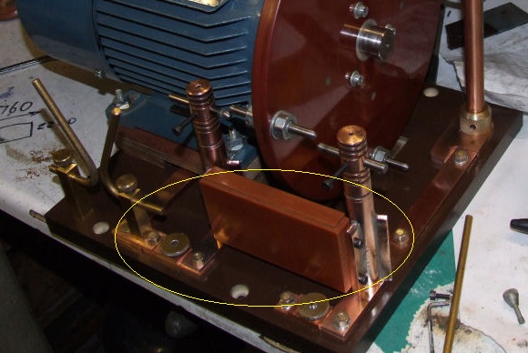
I had fitted a Tufnol bridging piece (circled) between the two electrode posts to stop any movement, but unfortunately this flashed over during a run.
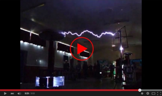
This was caught on video at the time:
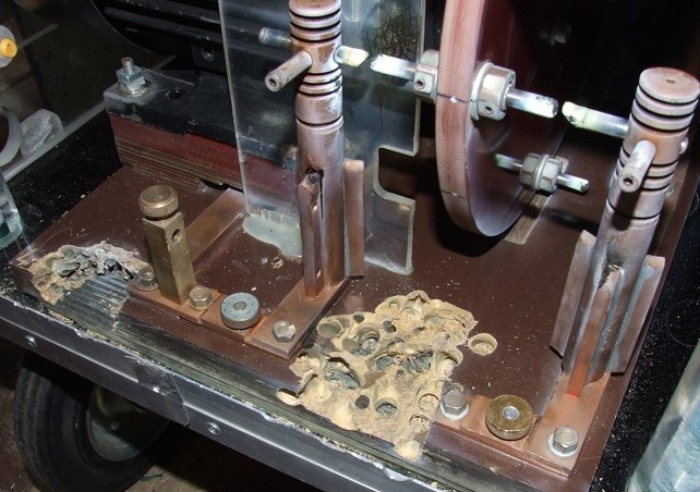
As soon as I had removed the bridging piece that had burnt up, the SRSG's base then also suffered a lot of damage, and despite ongoing repairs, this kept reoccurring.
This had all worked fine for two years, but now it seemed "all hell" was breaking loose every time I ran it! I therefore decided enough was enough, and as a temporary measure at the Teslathon I was attending, I drilled out large areas to get rid of the tracking. (As seen above)
.
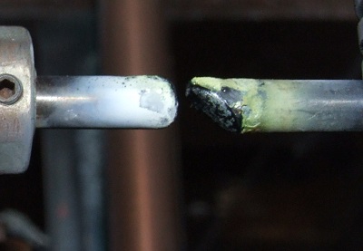
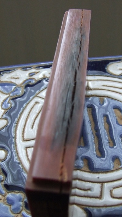
This is the result of 10 mins running after being gapped initially at 10 thou
The electrodes were ablating at a frightening rate, and the 0.25 inch Tungsten was actually melting (3422 degree C), so better heat sinking was required. I had also recently fitted a new motor for the SRSG, after the previous one had gallantly died in service.
So once again I pulled everything apart....
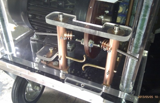
I was kindly given an inch thick sheet of Acrylic, to use as a base. Then along with the original copper busbars, and some new one inch diameter copper bar for the electrodes, I was back running again.
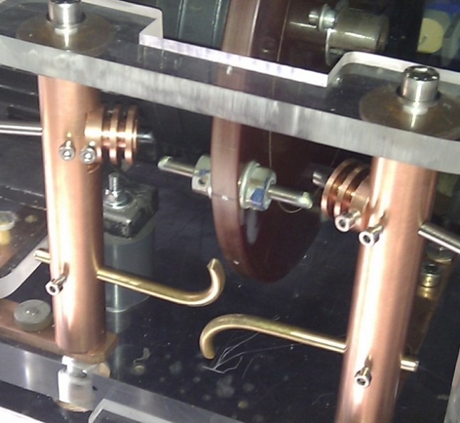
I also fitted a spacer between the two electrode holders, to ensure they couldn't move inwards. This should be able to withstand any heat that it's subjected to, as the considerable draft from the spinning rotor cools the copper electrodes nicely.
In an effort to stop the Tungsten electrodes themselves from melting, I have added some little copper heat-sinks with cooling fins.
Ideally I need bigger electrodes now (6 to 7 kW) but they will have to wait.
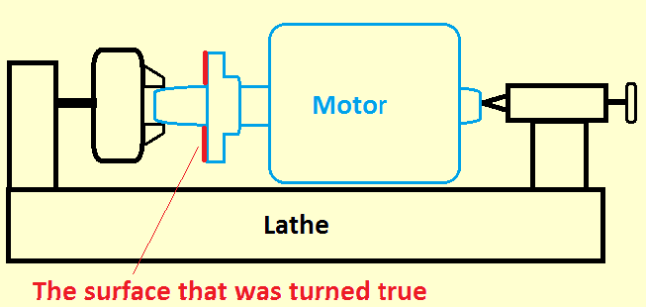
The rotor disc is mounted on a collar that I had turned up myself, and while it ran reasonably true on the original motor, it didn't run so true once it had been transferred to the new motor.(New shaft was a couple of thou undersize)
To solve this I mounted the motor shaft, with the collar fixed and locked in its final position, between lathe centres and turned the flange (shown in red)to run true.
I must admit to it being a far from ideal solution, especially as I was unable to remove the rotor from the motor to do it, but it worked fine. The motor casing spinning harmlessly because of friction from its bearings.
(Once the collar is in place and turned true, you are unfortunately unable to completely pull the motor apart again without removing the collar again. But it's easy enough to make another flange).