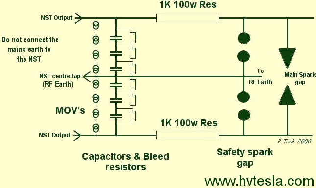
Resistors are 1000 ohm ceramic 100 watt rated, these will get warm, or even hot to touch, but that is normal.
MOVs are rated at 1800v, but the maximum allowable continuous AC voltage is 1000 volts according to their specification sheet.
The number needed in each leg of the filter will depend on your NST voltage using the formula (RMS volts * 1.414)/ 1000)/2.
For my 10,000 volt NST, that will equal 10,000 x 1.414 = 14,140 RMS / 1000 = 14 in total. So divide by 2 to get the number in each leg, = 7.
The capacitors in parallel with the MOVs are rated at 0.0033uF 1600v
The bleed resistors are 10meg 0.5w, the same as used in the MMC (Farnell: Order Code 129-2582).
A Terry filter is only needed if your running the tesla coil from an NST: due to their fragility. Its use is not so important on MOTs or OBITs, but the two large resistors would need to be a larger wattage to handle the increased current.
Without realising, I used this with my 5kVA DIY Transformer, only to find the resistors smoking!
The Terry filter serves the purpose of protecting the NST from any RFI getting into the NST and also any 'over voltage' situation that may occur. This is when a fault causes a reverse EMF to be generated by the primary, or the primary receives a strike from a streamer.
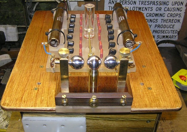
I also have a Safety Gap in the circuit as well. Hopefully one or the other will prevent me loosing, through damage, either of the NST transformers.
The Terry Filter takes its name from Terry Fritz who came up with the concept of adding this additional protection. There are several circuits you could use but Terry also came up with the idea of using MOVs in the circuit. MOVs are Metal Oxide Varistors. They have a rating so that when a larger voltage occurs, they break down allowing the voltage to short, in this case, harmlessly to earth.
See Wickipedia's Article on MOVs here.
For NST safety reasons the safety gap is set to fire when the voltage just exceeds the normal NST output voltage. While the main spark gap should fire at the normal NST voltage (often it is just below and depends on your capacitor size).
If the primary gets a strike the safety will short the damaging, very high incoming voltage, down to the RF earth and stop the voltage going onto the NST. If it does not manage to do this however the Terry Filter should also be just as capable in its own right of protecting the NST using the MOVs. The remaining components of the filter are to stop Radio Frequency Interference (RFI) getting into the NST and ultimately your house wiring.
Normally the mains earth is connected to the NST to protect someone if they touch the case when a fault has developed.
When using a NST for a Tesla though you should leave the mains earth connection off. This is because the RF earth connects to the NST earth instead. Connecting both would mean all manner of nasty interference from the Tesla getting into the houses's appliances.
If a fault did develop while the NST was running it would short down to the RF earth so would still offer some protection.
You should not be touching the NST at all when it is running, whichever earth is connected.
Another reason to avoid having it connected to the house earth is that the NST's earth connection also connects to the midpoint of its secondary coil, so it will have RFI (Radio Frequency Interference) on it when the safety gap fires.