Resonant Charging
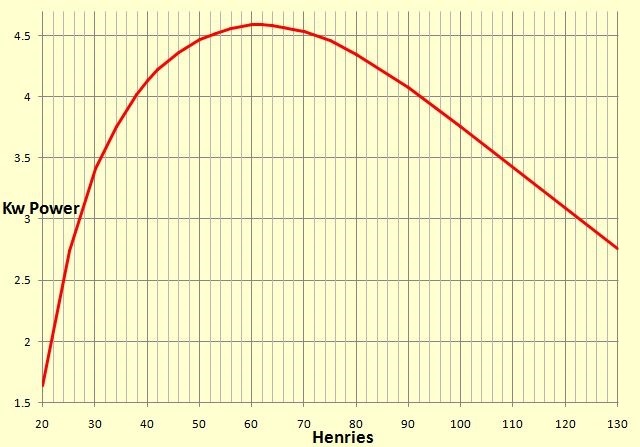
This graph gives the results of a PSpice simulation using a 72nF cap with a wide range of different ballast values. The aim being to find the most efficient combination. This result only applies to 200bps Synchronous gaps running on 50Hz.
See the full explanation below.
Static gaps with their random firing, are not too fussy about capacitance value, provided firstly, that there is enough charging current available, and secondly, that you are not using a NST, as these are not very tolerant of voltage rise and also use (in effect) an internal ballast. If you are using a NST then best to use a static gap, and make sure the value chosen does not resonant with the supply frequency, otherwise the resulting voltage rise could damage the NST.
However if you are running on a more robust power supply that also uses an external ballast for limiting current, you can use a SRSG (Synchronous Rotary Spark Gap) to take advantage of resonant rise. These prefer specific combinations of capacitance and ballast, that are designed to complement one another to get the maximum amount of power out.
An explanation of this can also be found on Richie Burnett's site, so his page Here, which inspired me to use the system, is well worth a visit.
200 bps SRSG Capacitor
With my 200bps SRSG the original capacitance value I was using was 72nF, so I carried out some PSpice simulations to find the best ballast value to use with that particular capacitor value, while using a synchronous 200bps rate SRSG.
Although using a smaller value ballast will allow more current to flow when used with an SRSG, that does not necessarily mean it will result in more useable power. This is because the Power factor (Wikipedia), comes into play, and it is this issue which Richie's Page on Resonant Charging deals with.
The graph above gives the results of using a 72nF cap with a range of different ballast values, and you can clearly see that with a 200bps SRSG, 60H to 62H of ballast gives the best power throughput when used with a 72nF capacitor. The required ballast figure would change if either the bps rate or the capacitance value changed of course.
This is "Resonant Charging", and as my coil's success is down to Richie's work, it's worth explaining in its own section.
Any rotary gap which is synchronous (SRSG) will fire at fixed pre-determined intervals (bps rate) and in fixed positions, relative to the AC mains voltage cycle. This is opposite behaviour to an Asynchronous (ASRSG) rotary gap where although it too fires at fixed pre-determined intervals, unlike a SRSG these firing points are no longer in fixed positions, relative to the AC cycle.
Because of this regular firing arrangement, the capacitor can charge quicker if the frequency is compatible with the charging ballast. This means differing bps rates will need different charging frequencies, if they are to achieve a decent power factor. A decent power factor will mean we have more power to use!
So Richie Burnett undertook numerous PSpice simulations to find the relevant frequencies for differing bps rates (an enlarged version of his graph is below).
The results found that a 200bps charging circuit achieves its best power factor when the charging components, (the MMC's capacitance & ballast's inductance), resonate at 75Hz.
(see Richie's original chart Here).
A slightly enlarged version is below: (Copyright is entirely Richie Burnetts)
Based on my own 200bps graph (top of page), my 72nF & 62H ballast's resonating frequency works out to round 76Hz.
So the charging circuit's preferred resonate frequency, with a synchronous rotary, is always dependant on the rotary BPS rate that is being used. So for resonant-charging to occur you need to match your charging components (ballast and capacitor) values, so that their resonant frequency is suited to the bps rate that you have chosen to use.
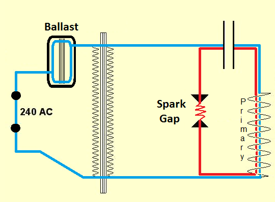
The resonant charging circuit's frequency path, shown in Blue, is determined by the ballast value (via the transformer coupling) the capacitor and primary coil in series.
In the blue circuit the small inductance value of the primary is insignificant however in comparison to the ballast's large value inductance, but it forms a vital part of the circuit.
In the red circuit however, this small primary inductance value is now very significant, as in conjunction with the main capacitor value, it determines the primary's resonant frequency.
The first graph on his webpage shows that a 0.9 PF or better can, for 200 bps, be achieved by a resonant frequency in the range of 65Hz to 80Hz. In reality I chose the higher end of this frequency range as this allowed me a better capacitor size (not unreasonably large).
Richie though favours a 0.85 PF for the reasons he states, but on lower bps systems, as in my case at 200bps, this can result in a rather large capacitor value being needed, which may be unreasonable for the charging current available, or for practical reasons.
Once you know the resonant frequency required, you then decide on a value for Cp that combined with the ballast value needed for your respective power level, will give the required charging frequency (The blue circuit above).
Richie's webpage is unfortunately unfinished after this stage, but he does give the full procedure needed in an earlier TCML posting of 16 Jun 2001 entitled "Resonant Charging Design" That post though has the two important graphs missing.
I have though made a copy of this post that You can find here This is not only the complete method
it also contains the missing graphs .
Richie's original TCML posting (with dead graph links) can be found Here