SRSG Staggered Electrodes 200 bps
The inspiration for this latest coil modification comes from Richie Burnett's Webpage on the subject. Much like Steve Conner has done great things for SS coils in the UK the last few years, Richie was doing the same for 'classic' spark gap coils when he was active in the hobby at the turn of the decade.
The theory of staggered or unevenly spaced electrodes has been around a long time and has been tried by others with mixed results.
Being curious I decided to give it a try myself and the only worthy information source was Richie site, so without stealing Richie's thunder or committing plagiarism of his web content a brief explanation of the theory follows, (for a more comprehensive explanation, with some good animations, you must visit his Webpage on this subject).
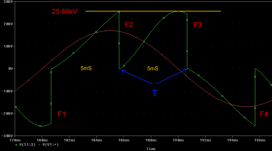
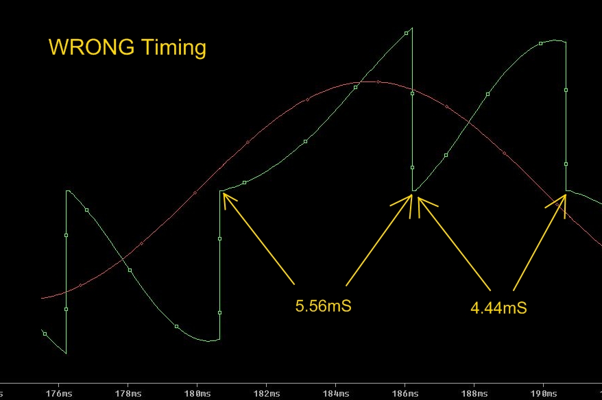
A quick summary is that a capacitor fed from a sinusoidal waveform will have a varying charging current available to it, dependant on where, with respect to the time-line, that the charge period occurs. After the firing at 'F2' (1st graph) we have the charge period 'T' during which we have a reducing charge current (red), which is not an ideal situation when charging a capacitor.
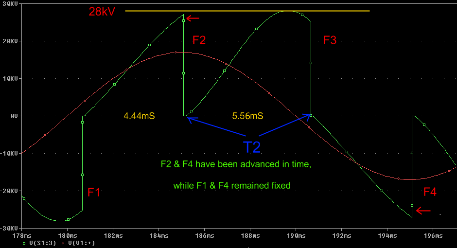
So by extending the period 'T' in the 1st graph to become 'T2' in the 2nd graph the capacitor now not only has a longer period to charge, it also starts at a higher point on the charge waveform as well, with the end result being a higher charge at the F3 firing.
So instead of having equal times for the charging period, we have shortened one period so as to lengthen the following one.
The same thing is happening in the negative cycle where we move F4 to allow the impending charge period there (off the graph so not shown) the same advantages.
(Note: The ballast and voltage settings have remained the same in both simulations.).
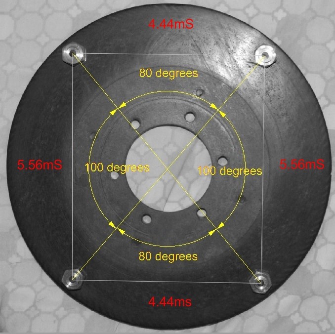
A 'normal' 200bps SRSG rotor would have the four electrodes spaced at an even 90 degree spacing.
For my first attempt at uneven spacing I followed Richie's advice, and like him went for a modest offset, as can be seen by the angles used.
The angles were calculated by (4.44mS / 20mS) × 360° = 79.92° and (5.56mS / 20mS) × 360° = 100.08°, but while getting that level of accuracy is easy with a lathe and a mill most coilers may not have that luxury, hence 100° and 80° are more likely to be the final result.
If though you wanted an increased offset like 4ms and 6ms, you would need to have angles of 72° and 108°, (calculated by (4mS/20mS) × 360° and (6mS/20mS) × 360°)
Regardless of which timing figures you choose to use, the position of the first electrode's hole may be critical. It will all depend on the method you have used for fixing the rotor disc to the motor's shaft. If your method allows you to easily reposition or swing the rotor disc around to a new position on the shaft, then the first electrode can go anywhere, but if like me the disc is keyed to the motor shaft, you need to carefully plan where you drill the first hole.
With a normal even firing SRSG, provided the phase controller can provide enough phase shift, it's not too critical # see footnote, but with the uneven timing arrangement there are now two different timing arrangements you could end up with. In my case this could be either 5.56mS followed by 4.44mS or 4.44mS followed by 5.56mS.
Initially it would seem that there is not a problem, as one timing will always follow the other, but remember the motor is now synchronous, so the motor shaft, and hence the disc, will always be in a fixed physical position in relation to the positive cycle, and as one timing is longer than the other, you need to ensure it's the correct one that occurs just after the sine wave's peak!
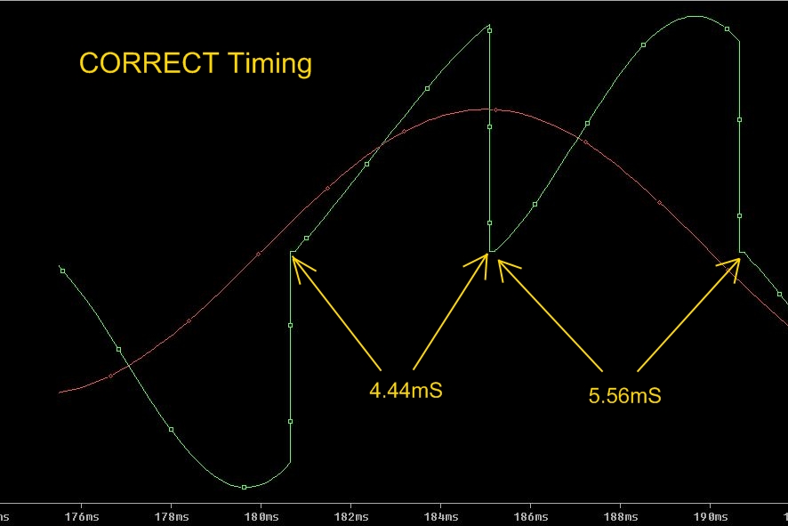
What we actually want is the first period in the positive cycle to be the shorter of the two timing periods (the same can be said for the first period in the negative cycle) (see illustrations below for the correct and incorrect arrangements).
![]()
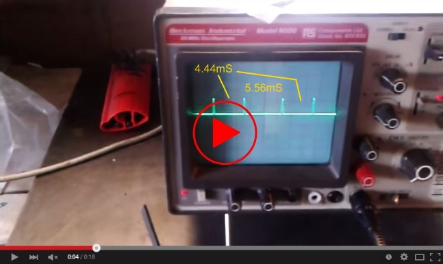
The longer time period can be seen between the two shorter periods.
(located in the middle of the 'scopes screen)
This was measured with the SRSG running and uses an infra-red beam broken by the electrodes.
Determining the correct position is best done with either a strobe light, or a vane on the rotor tripping an infra red beam whose output goes to an oscilloscope. Lastly there is the old fashioned simple hit and miss method of course, but that could take some time.
Don't get the matter of positioning confused by the fact that the rotor of a two-pole SRSG will always start in one of two positions anyway - each being 180° apart, but as one position will always be in the positive cycle and the other negative, and each physical half of a rotor disc is a mirror of the other, means that's never a problem.
Unevenly spaced electrodes will only have any real benefit on 200bps, and 300bps systems.
Although I haven't looked into the case of 300bps uneven working, bearing in mind the 'normal' output of a 300bps, where in half a cycle we have two peaks lower than the other, it looks like there is scope for improvement by adopting 300bps uneven working as well. In fact Richie includes a PSpice simulation file on his website, aimed at delivering three equally sized firings.
Oct 2015 Update:
I have now made a 300 bps staggered disc, See Here
So that's the situation so far, admittedly a fair bit of work is involved and best suited for those with the necessary equipment, but Richie's webpage gives promising gains in the power throughput of a coil adopting this method of working.
In my own case from doing PSpice simulations it should increase from 7.76 kW up to 9.11kW - (that's all gained from the offset arrangement, not from a change in ballast values, or capacitance).
At the moment that's all just figures on paper of course, so watch this space..................(results in early Nov 2015)
The result was that I had to make a jig and turn the disc on my mill (in horizontal mode). Lacking a faceplate of suitable size meant the disc vibrated badly, which has shown up in the surface finish.
Undaunted I decided to press on and use it, as dimensionally it was still ok. If it turns out the offset concept is worth pursuing, then it could easily be remade at a later date on a larger lathe.
Footnote: Even with a conventionally spaced rotor disc it's always best to check just how much phase shift your controller is capable of giving, and then to have the first electrode positioned where, without any phase adjustment applied at this stage, it's on the peak of the charging current's waveform. Then by using the controller you can adjust the firing point so it happens later in time. If you have chosen a completely wrong position initially, then it's possible the phase controller may not have enough shift to move it sufficiently - an unusual situation, but entirely possible.