Javatc Example of a Tesla Coil
Example:
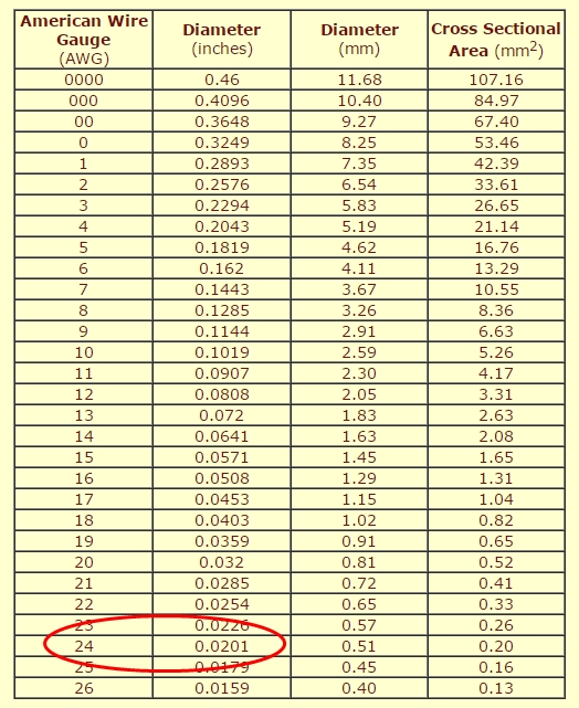
When you use Javatc it will firstly ask some basic specifications about the coil you're building, so you need to work out the secondary size, number of turns and wire size, which usually is around 1200 to 1400 turns of AWG 22 - 26 in size.
Using the wire gauge chart, we see that AWG 24 wire is 20.1 thou diameter, add in the varnish insulation and it will then be around 23 thou. Hand winding will probably on average give a 5 thou gap between turns, so say 28 thou as the overall thickness of one turn.
Therefore a 1200 turn coil will be 1200 x 0.028" high at least. This is 33.6", and allowing 3" of unwound tube each end, you need a tube at least 39.6" long. The 33.6 inch winding could use a 4 to 6 inch diameter tube, so we will settle with a 6" giving an acceptable aspect ratio of 5.51.
Next we could decide on the number of primary coil turns, but that will be affected by the value of your capacitor, which in turn is influenced by your power supply. So the power supply is the next consideration, which for a first coil is best to be a single NST, which would typically be capable of charging a 20 to 25nF capacitor.
Before we enter this basic data it may help if you also have a rough idea of what the software is doing and why, plus also you need to know these details to Tune the coil properly when it's built.
There are four main components to consider and the product of two of them (the main capacitor and primary coil inductance) will need to give a resonant frequency that matches the frequency from the other two (secondary inductance and toroid capacitance).
Let me quickly explain ...............
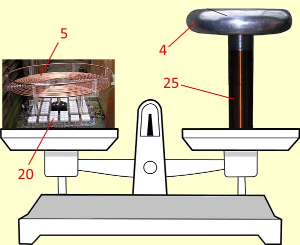
To make a simple example we will just use some imaginary units on each side of the scales:
A simple equation like 20 * 5 = 25 * 4 gives a sum of 100 = 100, as like a set of scales, each side balances the other.
If we now give our four components mentioned above these values and place them on the scale pans, on the left hand side we have 20 'units' of the main capacitor, and 5 'units' of primary inductance, while in the right hand pan we have 25 'units' of secondary inductance and 4 'units' of toroid capacitance.
So whatever the overall value is one side, it would seem that by altering a couple of values on the other you can make things balance. Well yes - but that's not really practical when dealing with fixed size components like toroids or secondary coils or even main capacitors, so in practice we adjust the easiest thing: the primary inductance, as this is just a large spiral onto which you can quickly and easily tap at any point to get different values.
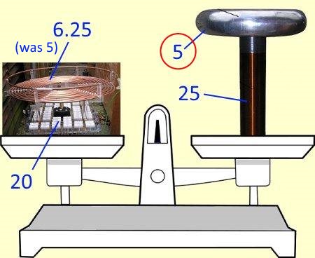
Taking the example above a bit further let's suppose we built a bigger toroid and its size now increased to '5' units. On the right side we still have the original 25 'units' of secondary inductance but now we have 5 'units' of toroid capacitance, giving us 25 * 5 = 125; an increase on the right side, while the left side (20 x 5) still equals 100.
The only way to alter the right side now would be to rewind the secondary to 20 'units' - but that's obviously not practical!
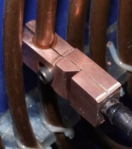
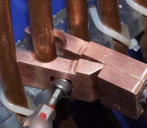
Therefore we need to alter the left hand side to also equal 125, but we want to keep our '20' value capacitor as that's not very easy to change, so instead we would change the primary inductance value, which simply involves unscrewing the tap (picture below) and reconnecting somewhere else to give us a new value of 6.25 units. Then 20 * 6.25 will equal 25 * 5, or 125 = 125.
That's an extreme example though as often you may find there is only a small difference between the values of the two sides, so only a tiny adjustment to one side is needed, which can only really be done both quickly and easily by moving the tap point on the primary coil again.
There is more about this on the Tuning Page
As most coil's values fit within a limited range (secondaries are usually between 10 to 100 mH, capacitors would rarely be more than 150nF, toroid capacitance is in pF, etc) a primary of 10 to 15 turns should handle most setups.
For my own thoughts on the matter of the best number of primary turns see Here
In reality the formulas used are more complicated than our simple examples above, and what we actually have is this:
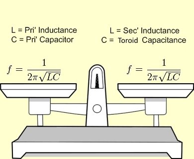
Fortunately software (see below) does this for you!
The point of explaining all the above was to give you the theory behind tuning the coil later on and to show how one component value, very much depends on another.
Javatc
We decided you're using an NST, and you have your secondary sizes sorted out, so then work out the physical size of the toroid that you are using or what you think you will be able to build. Toroid size information can be found Here, while build information (2 different methods) is Here and Here.
Because you are using just a single NST as the power source, let's say your capacitor is around 20 odd nF, as any larger may not charge fully from just one NST unless it's a higher output current unit (in excess of 60mA).
The primary spiral will be using an estimated 0.25" diameter tube and have 0.5" space between turns. As the secondary is 6" diameter, we add an inch all around for clearance, meaning an inner primary diameter of 8" is needed (4" radius).
Now we will run Javatc and start to enter some details based on a figure of ten primary turns, it will then compute how many turns of primary coil you actually need with 20nF and also the coil's specifications.
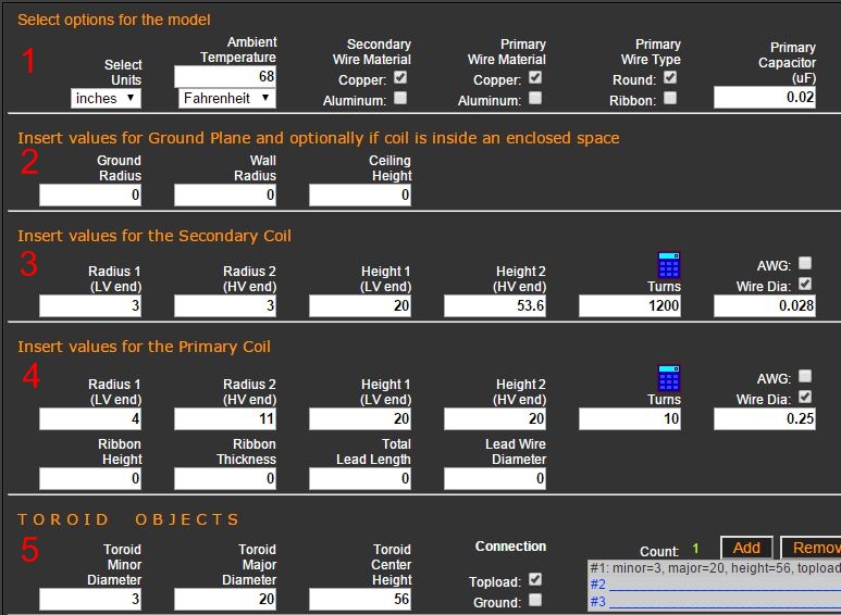
So starting with line 1 select (in this example) the 'inches' option, ignore 'Ambient Temperature' at this stage, then tick copper for both the secondary and primary 'Wire Material'. The type of primary is 'round' in our example, and lastly enter the size of the primary cap you're going to use. I went for 20nF so that is 0.02uF - you MUST get the units right here (0.1uF = 100nF or 0.5uF = 500nF).
Line 2 regarding 'Ground Plane' can be ignored in this test, so next it's onto Line 3 for the secondary coil details. Our example has a 6" coil so 'Radius 1' = 3" with 'Radius 2' being the same. 'Height 1' is the height above ground of the coil's bottom winding.
Now caution is needed here - we have a 33.6" tall winding with 3" left spare either end. So if the secondary was sat on a 17" high base, then the coil will have the bottom of its winding 20" above ground. 'Height 2' would then be 20" + 33.6" = 53.6".
Next enter our 1200 turns and the wire size we used. Choose either 'AWG' or 'Wire Dia' if you're entering the actual wire size in inches. If the number of turns is not high enough for that wire size in the space you've allowed it will tell you.
Conversely if the wire is rather thin for the space available then it will show up as too much gap left between each winding. But bear in mind if Javatc says it all fits, but there is only 2 or 3 thou (0.002 - 0.003") between windings, you will find you cannot actually wind the wire that close, so you'll either end up with a taller coil, or less turns. So common sense is needed when you check the winding spacing figure.
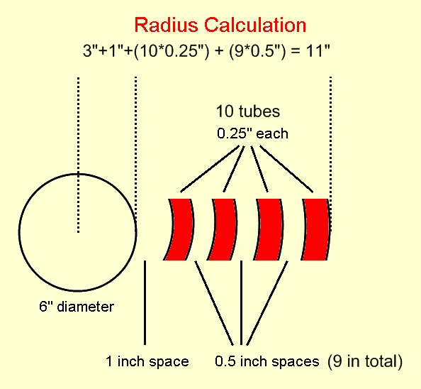
Line 4 requires the primary radius details calculated as shown above.
We had decided on 0.25" diameter tube with 0.5" left between turns, so with a 3 inch radius tube used for the secondary, plus 1" for clearance, that gave us 'Radius 1 (LVend)' = 4". Then we have ten turns of tube, each 0.25" diameter = 2.5" total, plus 9 inter-turn spaces at 0.5" giving 4.5" total. So grand total is 4" + 2.5" + 4.5" giving a total 'Radius 2 (HVend)') of 11" for a 10 turn primary.
The inner turn of the primary is normally set at the same height as the bottom of the coil winding initially, so enter 20" into 'Height 1 (LVend)' and as it is a flat primary (avoid conical types), the 'Height 2 (HVend)' will also be 20".
Then fill in the number of turns, 10, and wire diameter, or in most cases, the copper tube diameter (0.25").
Line 5 is for the toroid and we decided we would use a 20" major diameter with a 3" minor diameter. So set its centre height a couple of inches above the top of the secondary coil's winding to start with. There is a page on toroid information Here
Then choose 'Topload' for the connection, and then move across to where it says 'Add' and click there to input the toroid details.
If you were using stacked toroids you would then go back to the size boxes, change the details if needed then click 'Add' again so the second toroid details would appear underneath the first lot.
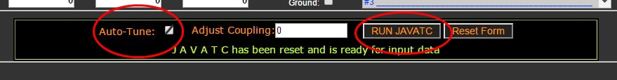
Now scroll down the page till you see the above, and then put a tick into the 'Auto-Tune' box, leave the 'Adjust Coupling' as zero, and hit the 'Run Javatc' button.
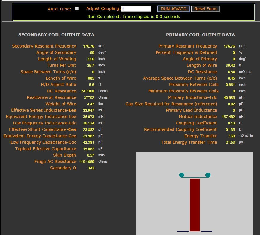
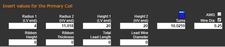
Here we see the output that Javatc gives us, also because we chose 'Auto-Tune' the software worked out the primary turns needed so that the primary resonant frequency matches the secondary resonant frequency. The figure it worked out is now shown in the primary input box, where you will find your original figure of 10 that you entered has now changed to this new figure (see below). This is what you will use for your tap position. Looking below you can see it has now changed from the original 10 turn setting you entered, to 10.025 turns, along with the corresponding outer radius difference as well.
Javatc comes with the option to load a sample coil as well, allowing you to see how the program works. You could also just enter the secondary details and run it to get partial results, the same with the primary etc.
By including your power details (entered further down the page) the program will let you know if your capacitor value is going to be resonant with the mains frequency.
In case of confusion for those new to coiling, we know the main capacitor forms a resonant circuit with the primary coil while it's discharging, but while it's charging the capacitor is also capable of forming a resonant circuit with the mains transformer that's charging it. Now while we wanted resonance between the primary and secondary circuits, it's best to avoid the capacitor resonating with the mains transformer, as the voltage can rise too high and blow the transformer power supply, especially if it's an NST which can be fragile sometimes.
Notice I said "it's best to avoid", as if the transformer can handle the voltage, it then gives a nice boost in performance. Try at YOUR OWN risk though.
I have successfully used this resonant charging arrangement on my 8 inch Phoenix coil, but it is powered by a
Pole Distribution Transformer (PIG) of the type you see on poles in the streets, and those are built to very rugged specifications and thus able to handle any over-voltage situation. More on this on another Page
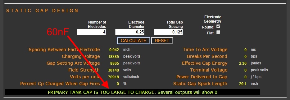
Javatc also has provision to enter spark gap details as well, be it either a static gap or a rotary. For this to work without filling in all the coil's details like we have above, you need to just enter the capacitance value you're using, the transformer details, and details of the spark gap itself.
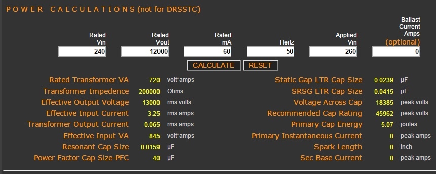
Above: We have now entered some details into the power section, to gather information on the transformer, this output will also be used for the static gap's data as well.
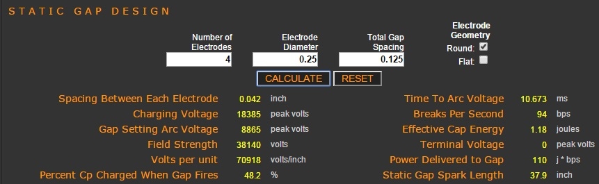
Above:This is the details of the static gap. For this section and the power section above you just use the 'Calculate' button in the relevant section.
Apart from these two sections the only other entry needed for the static gap was the size of the primary cap size (30nF), the input for this being located up at the top of line 1 (far right) which we filled in earlier. All the other detail for the primary, secondary and toroid are not needed for this calculation and the program won't ask for them if they are missing.
It's a great program and well worth some attention, all credit going to the American coiler Bart Anderson its creator of course.
DC resistance = 60.9 ohms
Inductance = 81mH
Q Value = 318
Aspect ratio = 4.32:1
Weight of wire = 4.26 pounds
Weight overall = 17.6 pounds
Winding length = 34.21 @ 40.8 tpi
Number of Turns = 1395 of AWG 24
Length = 2895 feet (0.54 miles)
Estimated voltage = 686Kv
Resonant freq (with Toroid)= 82 kHz
Primary = 72 kHz (approx')
-----------------
MMC:
Size = 101nF
Voltage Rating = 36Kv
Arrangement = 12 x 18 in series
Capacitor Type = CD 942C20P15K-F
Individual Rating = 0.15uF @ 2000v DC
-----------------
Rotary Gap:
BPS = 200 SRSG, John Freau controller
Motor = 2HP @ 3000rpm
Disc size = 10 inch overall
Electrodes = Tu 0.25-inch (4)
-----------------
Transformer:
Transformer = 250v input, 11.55Kv out
Transformer used at 263v / 12.15Kv
Ballast = 550 m/a for 6Kw+
-----------------
Toroid:
Weight = 20 pounds
Size = 34.64 inches x 8.34 inches.
Height = 6.25 inches above secondary
Centre line = 75.8 inches high
Overall height = 79.8 inches / 6.66 foot
Best Performance = 10 feet 6 inches
Usual Performance = 8 to 9 feet
The basic specifications of my coil:
Somewhat out of date though as the MMC is now 125nF and the ballast value changed for around 7.5kW.
Also the toroid I normally use now is a borrowed item measuring 50" x 11". The change in performance from using this much larger toroid was quite significant.