MMC Capacitor
My latest MMC uses Cornell-Dubilier's 942C20P15K-F arranged in 5 trays (one not shown) each tray giving 25nF capacity, rated to 36kV.
This gives a total of 54 caps per tray for a grand total of 270 caps for the 5 trays.
High voltage capacitors that can survive the grueling conditions of a tesla coil are hard to find, and therefore inevitably expensive if you do manage to locate some. Making your own rolled poly capacitor is another option, but this option rarely tends to be successful for very long.
Nikola Tesla (1856 - 1943) used salt-water capacitors which consisted of wine bottles with a brine solution in them. This option will work and it can also be very cheap if your short of funds. However they are not very efficient. Glass has very high losses when it comes to RF frequencies, so your coil's power output will be down. It is also difficult to estimate the value of capacitance that you have made, important when it comes to tuning, unless you have a suitable meter capable of measuring the capacitance.
The option that a lot of people use is to create a MMC or Multi-Mini Capacitors. These consist of quite a few lower voltage rated capacitors joined in a series/parallel combination. This means that 10 individual capacitors each rated at 2000v, could now handle 20,000v being applied across their series string of 10. The drawback is that capacitors behave the opposite to resistors in respect of their overall value when connected in series.
This means that once you have enough capacitors in a string to meet the voltage requirement, you then need to keep adding identical strings in parallel to bring the capacitance value back up to what you desire. This is illustrated below:
The difference is mainly to do with the connection onto the end of the plates, and it has been found the latter type can suffer from failure, unless the peak current is kept within the capacitor's specifications. Currently I use 125nF and power from a Pole Distribution Transformer or 'PIG' as they are often called, but these caps are just as useful for a single NST set up, although with a much reduced overall value.
These can be difficult to source outside of the USA however, and you may need to import them. In the UK Richardson Electronics provided the majority of my own.
A clumsy accident occurred in which a piece of scrap wire dropped across the MMC, resulting in this one single cap (a Cornell- Dubilier 942C20P15K) ending up being connected across a 12Kv 'Pig'.
The centre immediately blew out and was found to be completely carbonised.
The lesson learnt is not to put 12Kv across a 2Kv capacitor, and more importantly, also make sure no pieces of scrap wire are left unaccounted for!
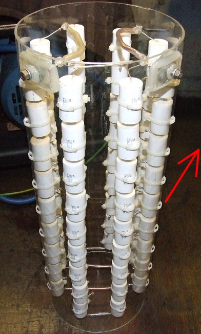
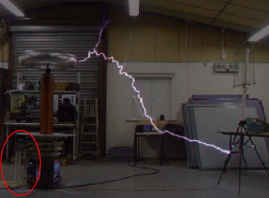
Circled above Another way of mounting many capacitors in a small space!
Before I was using the five trays shown above, I had a 72nF MMC that needed another 30nF, but with no room to do so, hence the circular MMC.
The reason for the increase to 100nF, was Richie Burnett's: Resonant Charging advice, see also More Detail in a TCML Post
Richie Burnett's resonant charging ideas relate to the fact that with a synchronous RSG, rather than the resonant frequency of the charging system being solely dependent on the mains frequency and ballast value, it is also affected by the SRSG's bps rate.
I have two pages on this site that deal with this subject:
Resonant Charging (1) & Resonant Charging (2)
Based on Richie's advice I therefore needed another four strings of capacitors bringing the total number being used to 216 (12 strings of 18 in series.
The circular arrangement saved space and avoided having to rebuild the whole coil assembly where the existing capacitors are presently mounted.
There are 76 capacitors in this MMC occupying a floor space of only eight inches diameter.
The easiest way to assemble the strings when using this method is to construct them externally, and then put them in once assembled. They were then held in place by cable ties passing through holes drilled in the exterior.
The finished auxiliary MMC measured 33.8nF (expected value was 33.3nF).
The replacement of a single capacitor merely involves cutting all the cable ties that secure that column, and desoldering the string top and bottom. You can then easily work on the removed string to replace the faulty item
The four strings each consist of eighteen in series. Each vertical column of capacitors consists of nine units with a link across the bottom to its corresponding partner on the other side.
The coil to MMC connections are the two nuts that can be seen at the top at the 4'o'clock and 8'o'clock positions.
There are several programs that will work out the overall value of a MMC's parallel / string arrangement for you. One of the best for MMC calculations is TeslaMap. It runs on Vista, XP 32 & 64 bit systems. In its menu goto 'View' >> 'MMC Calculator'.
A very important thing to remember is to try and fit bleed resistors across each capacitor. I have used 10 Meg 0.5 Watt axial thick film resistors.
(Farnell Order Code: 129-2582).
The purpose of these is to discharge the capacitor after the circuit has been switched off. Capacitor banks can be fatal if care is not taken. Just because the circuit was switched off some time ago (hours, or in extreme cases even days!) does not mean to say that the MMC does not still retain a charge.
As the transformer's secondary winding is wired across the MMC it should discharge naturally, but if a disconnection fault had occurred and stopped the tesla coil, you may well just decide to pack the coil away for the day with lethally charged capacitors waiting to bite you when the situation next permits.
Capacitors can also regain some of their charge even after they have been discharged. The process by which this happens is quite complicated but having found out personally, I can assure you it can happen.
It is most important that the bleed resistors are sufficiently spaced away from the body of the cap to avoid any flashover to the outside layer of the cap's body (been there, done it, got the T-shirt!), likewise the capacitors themselves should be suitably spaced when alongside others. Mainly to avoid flashover between adjacent units (another T-shirt), but also to allow cooling air to circulate, and removal of dust - which could become conductive at 30kV+.