As this is the very heart of the tesla coil and one of the most prominent visual aspects of it, it's important to have it looking nice, as well as being both functional and efficient.
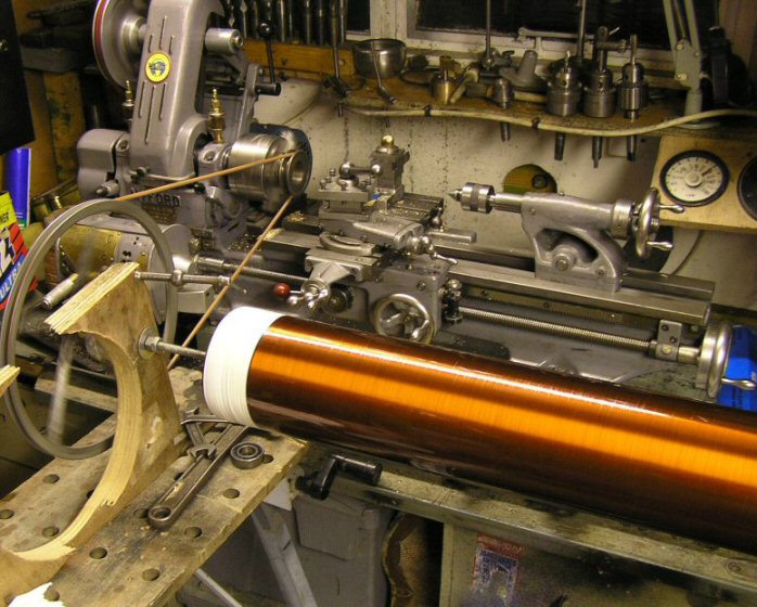
The setup that I used for winding my first coil.
You could rotate the coil by hand and wind at the same time, but it can be quite tedious and at times difficult.
This is because you need to apply [light to moderate] tension as you wind, whilst at the same time ensure that each turn of wire is snug against the previous one, as shown further down this page.
The reason being is that this ensures that the electromagnetic lines of force from the primary will cut a maximum number of turns of wire in the secondary and importantly, it will give sufficient inductance.
The magnet wire that I used on the four inch coil above was AWG 27, 0.355 mm diameter or 14 thousandths of an inch, which is about as small as I personally would wish to go. I found the handling fiddley at this size, and I also needed a magnifier to make sure the windings were staying close together, but some people are happy to go smaller than this if the coil demands it.
I was lucky enough at the time to have a lathe with a variable frequency drive allowing any speed I wished. So I engaged the lathe's back-gear and wound it at about 15 rpm. I also made up a foot operated switch, which meant I had both hands free to tension and guide the wire into place.
Those without a lathe often make up a winding jig by using gears (belts and pulleys) and a variable speed drill. Either way it is easier if there are two of you present, as tangles can occur etc.
For my later bigger coils, firstly a six inch then an eight inch, I used the lathe gearbox and leadscrew to guide the wire on. This left me to just apply some light tension by hand as it wound on.
After winding, the varnish can be applied slightly thicker than normal so long as the coil is then left turning whilst it dries. A fairly slow speed (~30 rpm) is all that is needed just to stop the varnish running to the bottom, while it is still wet.
The wire's diameter is determined by what size coil form you wish to end up with, which in turn is decided by how much power your HV source can deliver.
The steps therefore in deciding all this are:-
1: Determine the output power of your HV source (what ever it is you are using, NST,Obit, MOV, PDT, etc)
2: This power available will help decide the coil form diameter (this is not the wire diameter).
3: Based also on your HV source's power you can decide on the aspect ratio of the coil form. (The height of the coil form divided by the diameter. A 20 inch tall. 4 inch diameter form would have a 5:1 aspect ratio) See the Design Page for more information.
4: At one time people said the total length of secondary wire used, should be equal to a quarter of the coils wavelength. This thinking may apply to radio antenna but it is totally untrue of tesla coils, and has been proven to be false.
The minimum number of turns will be around 900 to 1000 but the figure of 1400 is usually considered a good working figure nowadays. This can go up to 1600 turns for the lowest power coils of under 0.5 Kva. These are very approximate guidelines that people have found to work for spark gap tesla coils.
5: Lastly it is simply a case of getting your calculator out, and using the wire tables find a suitable gauge that will give you the correct number of turns. The figures given in all the tables are for bare wire, so add around 10% to allow for insulation. Also allow for around 5 inches (2.5 inches each end) to be left unwound on the coil former.
Two important points:
1: Never take either ends of the secondary wire inside the tube it is being wound on. This always causes arcing inside and ruins the secondary coil.
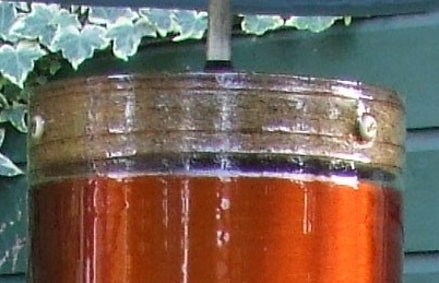
2: Always leave 2 to 3 inches each end of the former clear of the main winding, use this area to bring the ends of the wiring off in a spiral, as shown below.
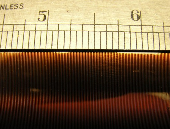
If you fail to count the number of turns, or loose count as you wind the coil, it is pretty easy to calculate the number afterwards.
Most cameras nowadays have a macro lens which you can use to photograph a section of the coil alongside a ruler. The image above has been reduced to one quarter of its original size for display on this webpage.
The original full size image makes it very easy to count the number of turns per inch that you have wound.
My 2nd Secondary
(6" diameter)
This was again wound on the lathe but this time the gearbox was engaged and the wire fed into place automatically as the saddle travelled down the bed.
As the coil was longer than the bed of the lathe it meant the operation had to be done in three separate sections.
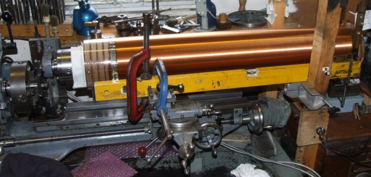
The coil was longer than the lathe.
In case anyone else is like me and a bit slow on the uptake sometimes, I will show an easy method for winding a secondary coil that is longer than the bed of your lathe.
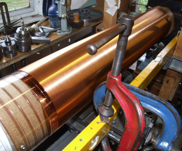
The lathe's main chuck in the picture above is actually driving another chuck mounted above it. It is this second chuck that is turning the coil. This arrangement is needed because the standard space over the saddle was only ~3 inches, and the coil being wound is a 6 inch.
The main problem though was that the bed of the lathe (a Myford) was just too short for the coil's length. To solve this I removed the tailstock and made my own support that I bolted further up on the bench. This support consisted of a wooden plug that was a tight fit into the end of the former. The plug then had a bearing fitted in its centre which revolved on a home made axis bolted to the bench.
For the wire feed I then bolted my spirt level (any straight, rigid rod would do) to the lathe's tool post and the wire was fed through a guide at the end (as shown below).
The saddle was then fed along automatically as the former revolved and pulled the wire on. Once the saddle reached the end of the bed, I just unclamped the spirt level, wound the saddle back, and re-clamped the spirt level back on again, but further on down its length this time.
I also found it best to apply slight friction by holding the wire to make it feed on smoothly. It's a very Heath-Robinson approach - but it worked.
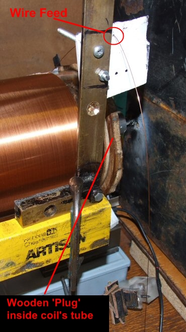
The wire passes through a guide hole in the plastic.
This contraption is clamped to a spirt level which is bolted to the lathe's saddle, and slowly advanced by its feed. The feed rate must be chosen to be close too, or preferably the same as, the wire diameter.
In my case I decided on the approximate wire diameter I wanted, taking into account the number of turns required, inductance value and overall length, and then the final choice of the wire diameter was matched to the closest suitable feed rate that the lathe could offer.
If your chosen feed rate is not a perfect match you can make adjustments while the coil is actually being wound, by winding the top slide back or forwards every so often by a few thou.
The end of the secondary tube is supported by wooden plug fitted inside the secondary former, that revolves on an axis welded to the black steel plate you can see. This in turn was bolted down to my bench.
This method, although long winded, produced a much neater winding than my first coil which, although it was turned by the lathe, had the wire placed on all by hand (shown at the top of the page).
After an incident with one of my neighbours leading to the destruction of the 6 inch secondary, I then successfully used a similar approach to wind my current 8 inch, aptly named "The Phoenix" coil (1400 turn 8 x 34.4 inch). This size however would be the absolute limit for my small lathe.