DIY Transformer (Page 2)
Remember: Transformers with high current can be Lethal.
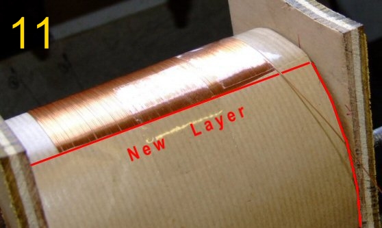
11: Adding the paper at the end of a layer
Here you can see how using the edge of the paper, you make sure that the wire is correctly positioned to start the next layer on top of its last turn. Also try and arrange that the paper joins are as close to the ends as possible. This avoids adding unnecessary bulk to the winding in its centre region. unnecessary bulk to the winding in its centre region.
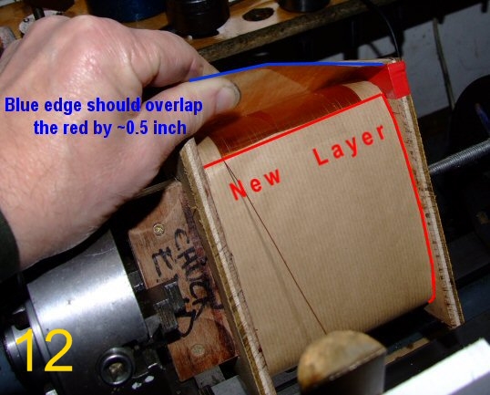
12: Fitting the paper
There should only be a minimal overlap of the paper's edge (Blue), but there must be at least some, ideally 0.5 inch or 1 cm.
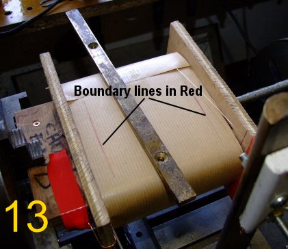
13: Guide lines
On each new layer I marked the extent each side that the winding would extend to. I left a clear half an inch at each end. This is to avoid a flash-over occurring at the edges, which can occur if there is insufficient paper. Do not use a pencil or black marker, both could possibly conduct the HV.
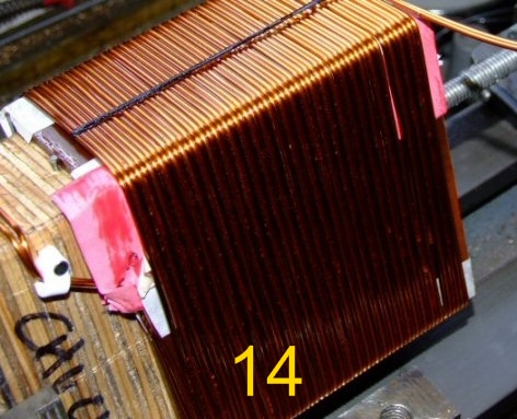
14: Securing the Primary with thread
This is not really needed, but it may stop the primary turns from slipping down.
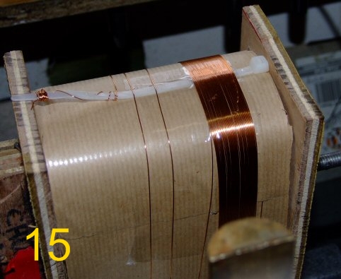
15: End of secondary wire being anchored
The method I adopted here was to use a simple cable tie taped across the coil. The secondary wire was then wound on top securing it. The raised end of the cable tie (to the right) will stop it from pulling out. I then made a small hole in the cable tie with a hot pin and threaded the wire through it and tied it off. You can then solder a heavier wire for the lead-out onto the magnet wire.
I had the thicker lead-out wire inside a piece of plastic tube, which I was able to slide down over the tapered end of the cable tie. This not only covered the soldered joint, but also made a stiff fixing to stop undue flexing of the delicate connection.
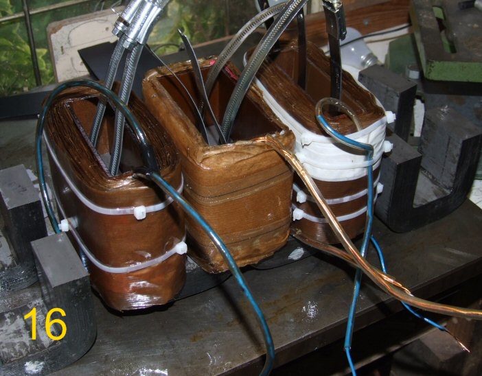
16: Ready to assemble
Originally the cores were held together by metal bands, but I found that very large Jubilee clips made a first class, easy to source, substitute.
I also found that the mating surfaces of the upper and lower cores had to be a good clean fit, and free of any old varnish or bits of bobbin dust from when you slide the top cores in place, otherwise it will affect the mating of the surfaces and give a different reading on an inductance meter, and ultimately the output current.
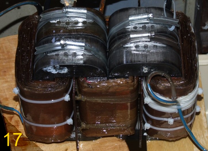
17: Ready for the oil
I re-used the old transformer oil again. I also had a large 6H oil cooled inductor which also donated some of its oil.
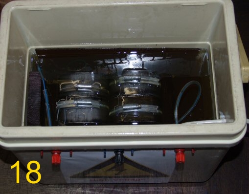
18: The picnic box was a perfect fit
I had spent quite a bit of time trying to find a container that was exactly the right size. At the last moment I spotted our picnic box languishing under the stairs.
In a flash out came the tape measure - perfect fit. Only then to be told by my wife that the box would be handy for a picnic anytime.
Perfect, now I had two good reasons for using it.
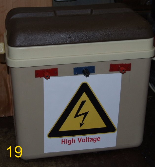
19: The finished transformer.
Was it worth it?
As an exercise, most definitely yes. I learnt a lot about transformer design and AC theory thanks to the web and support from various news groups. Also you don't realise the work involved till you build one yourself. They are not a quick day's work. You need to get all the materials ready to hand. Insulation paper pre-cut. Bobbins and mandrels made.
Also you most definitely need some form of winding machine that has a lead screw arrangement as getting the wires close together not only allows the maximum number of turns, but results in a better flux pattern.
Was it worth it financially ?
Absolutely NOT.
Magnet wire, especially the heavier gauge used for the primary, is not cheap, and you need a lot of it. But we don't build these things to make money do we (?)
I estimated I used approx' 2.25 miles or 3576 meters of secondary wire (0.4mm / AWG #26 / SWG #27). The current capability being 580 mA under oil.
The primary is a bifilar winding of AWG #14 / SWG #16. The normal current capability of this gauge is around 9 amps under oil. But the bifilar winding means it will carry 18 amps easily, with short runs at around 21 amps.
The maximum output is 10,900 volts at 537 m/amps this gives 5.85 kva. This draws up to ~21 amps at 276 volts (Variac on maximum) on the primary through the current limiting ballast shown above.
The weight of the whole assembly in the box with oil is 31 Kgs or 68 pounds.
Links I found useful for this project: (all active June 2015)
VERY Good Page with lots of info.
The correct formulas as used in commercial designs
Amperage rating for AWG wire
Wikipedia
Transformer Measurements
Transformer Theory
Phasing of windings
UK Magnet wire seller
Ballast Coils