How Tesla Coils Work
![]()
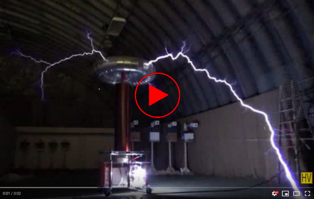
The biggest coil running in June 2018
This superb coil belongs to P Strauss with whom I also run my own 8" coil, meaning I often get the privilege of running this powerful 12" 100bps example.
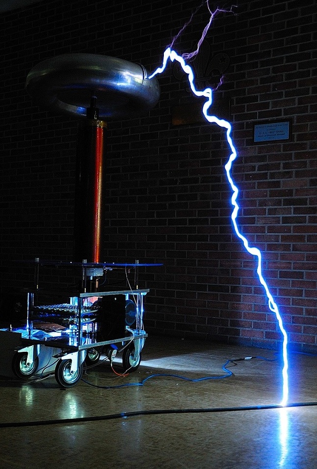

The 8 inch 'Phoenix'
In action at the Nottingham Gaussfest several years ago. Power was from a Pole Distribution Transformer (PDT) , and the coil was running a 200bps synchronous rotary with phase control.
Capacitance was 115nF provided by a pulse cap (65nF) and Cornell-Dubilier's 942C20P15K-F capacitors (50nF).
The coil has been updated since, with increased power (lower value ballast), more capacitance (125nF), and the use of a bigger (borrowed) 50 x 11 inch Toroid.
This has all added up to increased performance. Unfortunately the venues I currently attend all suffer from low ceilings, so bigger coils can never reach their true performance.
In an effort to overcome this, the coil was lowered in 2015 and at the same time was given the ability to run with offset SRSG electrodes.
This involves swapping my 'normal' rotor disc for a new 'off-set' version. To aid changing discs back and forth for comparison tests, the base unit layout was also altered to give quicker and easier access.
The practical work on this is now all done, with testing due in Oct 2015. In the meantime though I have added a new Web Page explaining the details.
Soft Iron core output voltage:
Vs = (Vp x (Sec turn / Pri turn)
Air Cored transformers are another variety and their output voltage is determined mainly by the capacitance and inductance values of its two coils, (the equivalent of the windings of a conventional transformer).
Air Cored output voltage:
Vs = Vp*sqrt(Cp/Cs)
Or
Vs = Vp*sqrt(Ls/(2 x Lp))
Vp = Peak Primary Voltage
sqrt = Square Root
Cp = Primary capacitance value
Lp = Primary inductance
Cs = Secondary capacitance value
Ls = Secondary inductance
Vs = Secondary output volts
The first part of my tesla coil is powered by a conventional 12Kv pole distribution transformer (aka 'Pigs').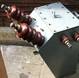
(Click the above picture for details of the transformer)
This then feeds into an air-cored resonant transformer, or as they are simply called..... a Tesla Coil.
To understand how a Tesla coil works you first need to understand
a couple of basic points about the components and terms used:
1) Inductors: (component)
The Tesla coil's primary and secondary coils are both inductors in electrical terms. When the current flowing through an inductor changes, it will create an opposing or reverse voltage.
Wikipedia Article
2) Spark Gaps: (component)
A sparking plug in a car is a basic spark gap, its break-down voltage dependant on the electrode gap size. Once it conducts, hot ionized air in the gap gives it the ability to carry on, so long as a current is flowing.
3) Capacitor: (component)
A good analogy for a capacitor is to think of it as a sponge, placed on spilt water and left to slowly soak it up. If left for a minute and then given a quick, hard squeeze, one minute's worth of soaking-up is instantly released in a fraction of a second.
In a Tesla coil circuit this so called 'soaking-up' stage lasts only a few milliseconds, while the 'squeezing-out' can be a thousand times quicker in a few micro (millionths) of a second.
Wikipedia Article
4) Resonance: (terminology)
The property of resonance is fundamental to the operation of Tesla coils.
A good analogy is a garden swing. If left to swing on its own it will do so at its resonant frequency, only slowing down due to friction and gravity.
If you stand behind the swing and push it just as it swings away from you each time, it will get higher with each subsequent push. This is because you are adding power at, and only at, the correct time-point in the swing's cycle.
You are therefore adding momentum at the same time interval as the swing's resonant frequency, this means the push you gave is in resonance with the swing.
Resonance does not magically increase the amount of energy, it only facilitates its transfer.
So if you're looking for tesla related, so-called 'free energy, or 'zero point' energy information, which some people seem to associate with tesla coils, this is not the site for you!
5) Resonant Circuit (terminology)
If a capacitor is placed across an inductor and voltage applied, you will have a resonant circuit. As the capacitor discharges, it sends current into the inductor that stores this as energy in its magnetic field. But as the capacitor discharges, the current into the inductor also diminishes.
This causes its magnetic field to collapse and generate an opposing voltage back into the capacitor, allowing the cycle to start all over again. The number of times that this 'back and forwards' cycle happens per second, is the circuit's resonant frequency, expressed in Hertz (Hz).
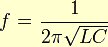
Using different capacitance and inductance gives different frequencies.
Note: Because of resistive losses the current reduces every cycle down to zero.
There is NO such thing as free energy!
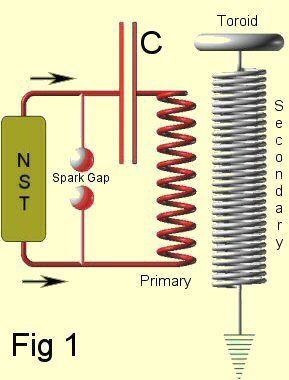
In the circuit of Fig 1 above, the capacitor ('C') is charged up by a high voltage source, like my example of the sponge soaking up water.
Once the capacitor attains a high enough voltage the spark gap fires and conducts (Fig 2 below). The spark gap is now a short-circuit that completes the resonant circuit (shown in red) of the primary inductor and capacitor.
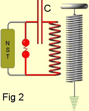
The spark gap firing is virtually an instantaneous discharge of the capacitor energy into the inductor and is like my earlier example of the sponge being instantaneously squeezed out.
The inductor (the primary) stores this energy in its magnetic field with its lines of force cutting into the secondary coil (another inductor) and induces a voltage into it. Once the capacitor is empty, the current flow into the inductor stops, and its magnetic field collapses causing a reverse current (now fairly reduced) to flow back into the capacitor again.
This back and forth diminishing cycle (called the 'Primary Ringdown') of capacitor to inductor and back, continues until there is insufficient current flowing to keep the spark gap conducting. The point to remember is that every time this primary cycle occurs, more energy has also been transferred away to the secondary, so the primary inductor's magnetic field stores less and less energy on each cycle.
Unfortunately every time the spark gap conducts, losses also occur in the form of heat and light, so you want the minimum number of cycles that are consistent with getting all of the available energy transferred to the secondary.
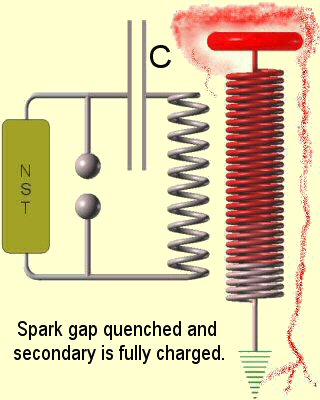
Usually after two, three, or possibly four cycles the majority of the energy has been transferred and the primary current has dropped enough to allow the spark gap to stop conducting (called quenching).
Once the spark gap has quenched it allows the capacitor to get a fresh charge and the whole affair can start again.
The amount of energy available to the primary (measured in Joules) is 0.5 x C x V^2
C = Farads, V = voltage that the gap fires at.
You can see here that doubling the value of C (provided your power source is robust enough) will give you twice the power. But doubling the voltage that the capacitor is charged up to will give 4 times the power, because the voltage value is squared, that's why if you want spark length it's best to go for a higher voltage power source.
While the primary circuit is resonating and transferring its energy, the following is also occurring in the secondary circuit at the same time .........
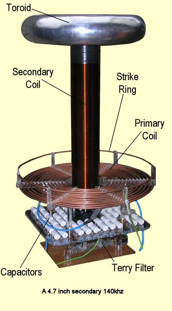
The toroid on top of the coil acts like a capacitor with respect to the surrounding ground. This is easier to see in the diagrams below.
Fig 1 is the same as Fig 2, because in reality the toroid discharges through the air to earth. If you now replace the toroid with the symbol for a capacitor (Fig 3) and re-arrange things, you end up with Fig 4.
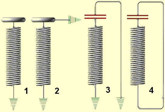
This means that the secondary coil (an inductor) along with the capacitance of the toroid also forms a resonant circuit, behaving much like the primary circuit. The secondary's energy is therefore also resonating back and forth between the coil and the toroid. However it does not dampen down the same as the primary does, in fact it is steadily increasing.
This is because at just the right point in time of its cycle (like you pushing that swing in the example) another magnetic field from the primary circuit, which remember is also resonating at the same frequency, transfers a bit more of its stored energy into the secondary circuit.
Therefore as the primary ringdown is occurring causing the primary to loose its energy, the secondary is gaining power, in what is called the Secondary Ring-up.
Remember the primary and the secondary need to have the same resonant frequencies for them to interact successfully (in reality there is a deliberate slight mis-match, explained elsewhere). Typically this is in the hundreds of Kilo-Hertz.
Eventually the voltage on the surface of the toroid at the top, rises so high that the toroid's curved surface cannot retain the charge anymore, and breakout occurs. This will either be a misty purple corona discharge or, if all components are suitably balanced to one another, a whitish solid streamer down to earth or into the air.
In a perfect Tesla coil once breakout has occurred this would be the end of the matter, allowing a fresh charging cycle to start all over again. What usually occurs though is that as the secondary's field starts collapsing it starts to transfer its energy back into the primary again. This is because the hot ionized spark gap in the primary charging circuit is still able to conduct the somewhat reduced energy now being returned by the secondary.
This means that any remaining energy in the collapsing secondary, that could have gone into prolonging the discharge, is wasted by being sent back into the primary instead. This can result in the whole of the primary to secondary transfer cycle occurring again, and in the worst cases even three of four times.
What is the problem with that you say? Well firstly it is better to have all the energy forming one high charge, rather than several cycles of successive diminishing charges.
And secondly no new energy from the power source can be added to the circuit until the spark gap has quenched, and that can't happen until the present cycle stops.
There are various ways to overcome the problem of these unwanted cycles. In a so called static spark gap you can use either Suction or a fan to both remove the hot ionized air from between the electrodes and also cool them, as both actions help quenching.
Another method is the rotary spark gap. In these the spark gap consists of a fixed electrode while the other revolves, much the same as a distributor in a car engine. These spark gaps come in two different types. Asynchronous [ARSG] and Synchronous [SRSG], the latter being where the position of the rotating electrodes in each revolution, is directly linked to the mains frequency cycle, whilst the Asynchronous system is not.
With the synchronous system, you arrange for the revolving electrodes to come into alignment with the fixed ones when the AC cycle is near its peak (normally you aim for approx' 1mS or so after the peak). This allows the capacitor to discharge into the primary, at the optimum time in its charging cycle. The revolving electrodes also disturb the surrounding air to assist with their own cooling.
It's not the actual separating action of the revolving electrodes that quenches the arc though, this is because a spark can be stretched quite significantly once struck. Quenching occurs naturally at one of the primary notches, and hopefully this quenching notch will occur once the electrodes have moved sufficiently out of alignment, before the capacitor has recharged sufficiently to start the cycle all over again.
Asynchronous gaps, because they use revolving electrodes, also fire at an even rate, but in their case it is independent of where the AC cycle is. This means that the capacitor may not be fully charged at the time of firing. It can also mean that the opposite situation can arise where a higher than normal voltage can occur across the capacitors and the HV supply. For this reason Asynchronous systems should not be used with an NST, because they can sometimes be rather fragile when subjected to high voltage spikes.
Even rotary spark gaps have their short-falls though. As the voltage that the spark gap handles is increased the timing tends to become advanced. This is because the higher voltages from the bigger transformers (usually 15,000>) means the spark is able to jump the gap between the static electrode and the rapidly approaching rotating one, before they actually line up.
With a Synchronous spark gap [SRSG] this can be overcome by adjusting the Phasing of the AC input to the motor using inductors and capacitors. This way the position of the revolving electrodes can be finely adjusted in relation to the fixed ones.