Measuring Coupling
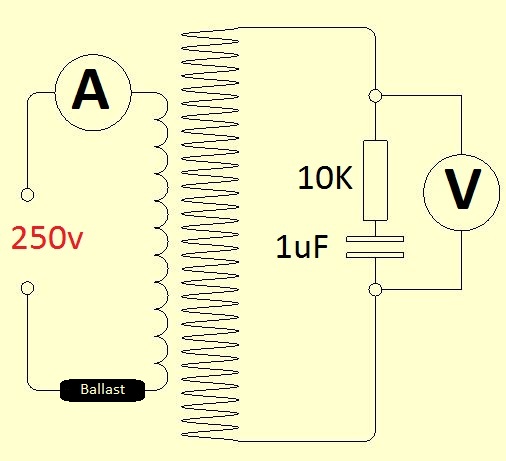
Left: The Basic Circuit
There are several ways to measure the mutual coupling (from which you can calculate the 'k' factor) of your tesla coil, and this method seemed to be the easiest, but also a fairly dangerous method if you do not take care.
For that reason I do not recommend that you follow my method, but if you do decide to do so, then the risk is entirely yours.
The primary coil is completely disconnected from the tank circuit to enable you to apply mains voltage across it. It will however need to be ballasted with a suitable resistance to limit the current to around 6 to 10 amps. The less capable your voltmeter is to read low voltages accurately, the more amperage you will need to apply. The typical voltage that you will be reading is from 0.5 to 1.0 volt, preferably to three decimal places, so an accurate digital voltmeter and ammeter will be needed for accuracy.
The method simply involves reading the voltage induced into the secondary coil by the mains current flowing in the primary. These two figures, along with the primary and secondary inductance, then allow you to work out both the mutual inductance and coupling factor (k).
For the ballast you will need something like a heater element rather than a light bulb, as they do not have a stable resistance. As I wanted to move the primary position and get a graph of the results, I chose a fan heater for the ballast so that I could leave it running all the time and keep its resistance stable.
Because I wanted accuracy I also decided to read the current after each voltage reading, so I had a switch whereby I could switch the ammeter in and out of the circuit without stopping the fan heater.
I found the secondary voltage was never steady and would alter by 4 or 5 milli volts, so as my DVM has a record facility I took each voltage reading for 20 seconds and then used the average function. The same procedure was used for the current which would vary by a similar amount in milli-amps, but to stop the DVM overheating I took 10 second readings instead. Slight inaccuracies in the current readings will have much less impact on the result as would an inaccurate voltage figure. Also if possible it is best to use a true RMS meter for reading the primary current.
The secondary tends to pick up background noise despite the capacitor and resistor shown, in my case this was 4 mV. For this reason it is best to work outside and note the secondary's background voltage before you start and again when you finish, and adjust the results if it is needed.
The formula for the mutual inductance value is:
M = V / (w * I)
Where:
M = Mutual inductance (Henries)
w = Line frequency, Radians per second (314 for 50 Hz or 377 for 60Hz)
I = Primary current (Amps)
V = Induced Secondary Voltage (Volts)
The k Factor can be found from:
k = M / sqrt(Lp * Ls)
Lp and Ls being the inductance of the primary and secondary coils in Henries.
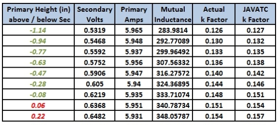
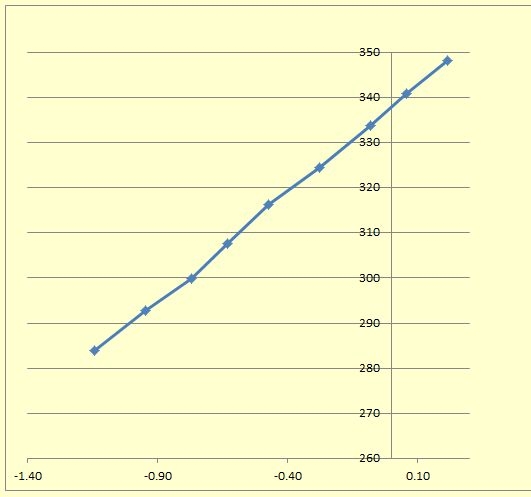
The Results
The results plotted to a reasonably straight line and also followed the results given by JAVATC, although that program gave a slightly higher result, but not to any significant amount.
Effect of adding an a Acrylic shield to the primary
The primary now has a 5 mm thick Acrylic cover or shield added to protect against streamer strikes (Here), and I wondered on how much effect this would have on the coupling factor. Anecdotal evidence suggested it would have little effect, but I wanted to see for sure, so I repeated the test above with the shield in place.
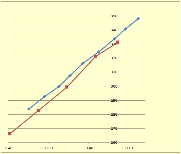
In the end it proved quite difficult to mount the primary securely at the same heights as had been used for the first experiment, and as you can see from the results (red curve) the measured primary height would not appear to be correct.
This is because according to the graph the absence of the Acrylic shield actually lowered the inductance coupling, something which is clearly wrong.
However looking again at the figures and revising the height data in Excel enough so that the coupling would have been affected significantly, would mean that I would have to have been at least half an inch out in my measurements, a sizeable amount, and fairly noticeable if that had been the case.
This was in fact the second time I had done this exercise and on the first occasion the mutual inductance figures for both with and without an Acrylic shield were virtually the same, so i feel confident in saying that there is little if any adverse effect using a shield of 5 mm Acrylic. How this would be affected by other materials or different thicknesses is something that I cannot answer.