Power Factor Correction
'Apparent Power' (VA - Volts Amp)
Despite what the item's power consumption is shown as on the label, 'Apparent Power' is what is "apparently" being drawn by your circuit in the real world from the power station, and forms the Hypotenuse in the power triangle (the product of the 'reactive' and 'real' power). A voltmeter and an ammeter will give this figure.
'Real Power' (W - Watts) also called 'Active Power':
This is the part "actively" engaged in "real"ly doing any work, and is the triangle's baseline (will be LESS than the VA product above).
'Reactive Power' (VAR - Volts Amp Reactive) also called 'Imaginary Power':
This is the vertical axis and is the power component not doing any useful work that needs to be reduced and compensated for, so it gets added to the 'real' power component.
As my power levels increased, power factor correction was becoming an issue I had to tackle. There are numerous sites on the internet explaining the theory so I'll leave you to find most of them, but the one I particularly liked is This One with the cosine angle explained with a nice analogy involving a canel boat and a horse!
While for a useful calculator I would recommend This One which is what I am using below.
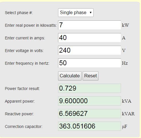
Using the calculator given in the link I entered the following details that you can see. Unless you have a Watt meter or a PF meter handy, the 'real' power has to always be a guess. So based on the coil's performance and John Fraeu's estimate for streamer length versus power, I felt that as the coil has achieved 10 foot, and can draw 40A+ it was actually achieving around 7kW max, so this was used as my estimate.
The voltage and amperage I knew from my instruments, and this accurately gave the 'Apparent' power as 9.6kVA, which with an estimate of 7kW gave an uncorrected PF of 0.73. Bearing in mind I ran a synchronous RSG and used resonant charging it seemed a not unreasonable figure. Trying various levels between 6 to 8kW (my lowest and highest estimates that the coil is giving) for the estimated 'Real' power, gave a capacitor size of between 293uF to 414uF being needed to reduce the wasted reactive component. Less 'reactive' power meaning more 'real' power available for the coil.
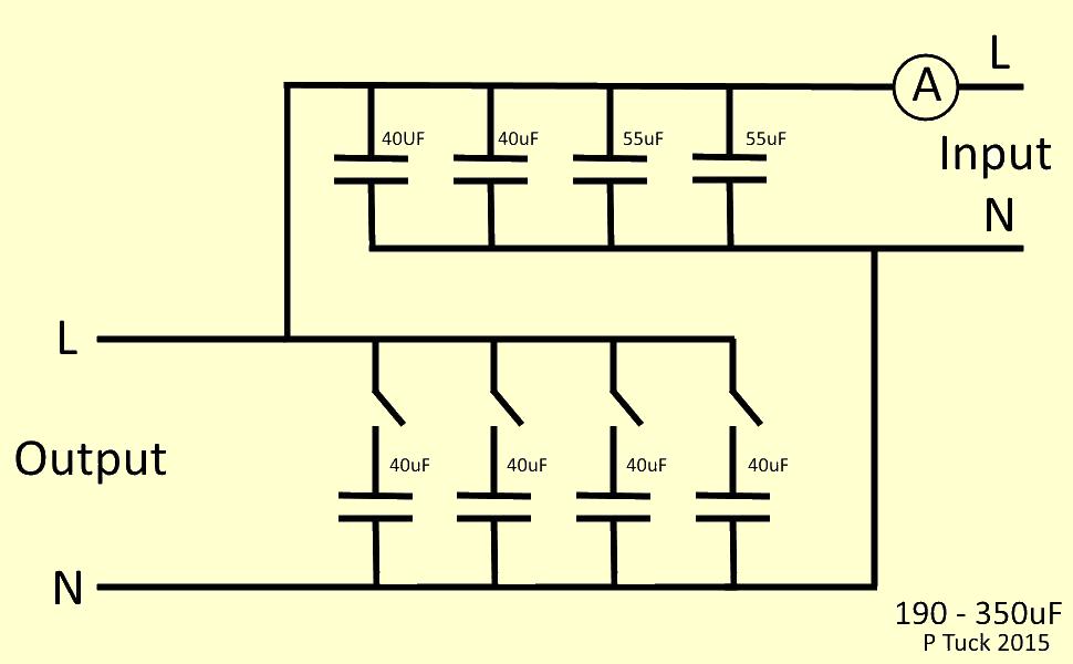
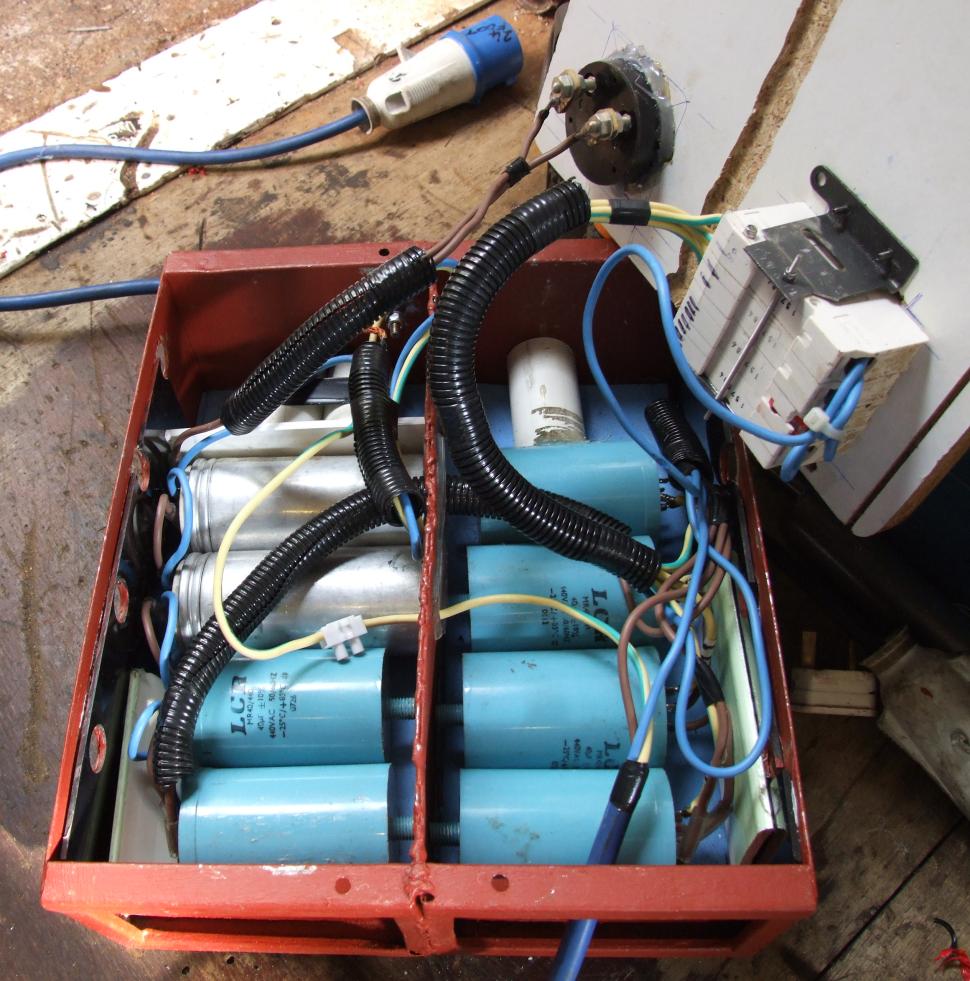
After some research on the web it seems extra compensation past the ideal figure and the Reactive power may not only start to increase again, but can cause other problems to occur such as voltage spikes, while not enough will mean the circuit will still be carrying too much reactive current. I therefore decided to have a figure of 190uF permanently connected with 4 additional increments that I could switch in or out. The reactive current should then slowly drop as I switch some capacitance in, but conversely, increase if I switch too much in!
Unfortunately I can only measure the 'apparent' power, so I'm hoping the coils running performance from its increased 'real' power will give an indication of the ideal amount needed.
Eventually I settled on four increments, giving totals as follows: 230uF, 270uF, 310uF, 350uF. Ideally I could have done with larger capacitors, as 350uF may still be too small, but no doubt these will come along one day via Ebay.
The important thing though is that even a lesser amount than what you ideally need, will still help matters.