Rebuild of 8 Inch Tesla Coil (3)
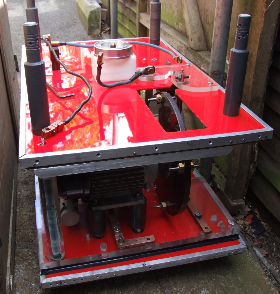
Top shelf and capacitors removed.
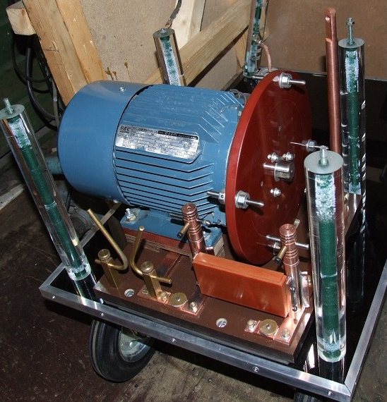
After many design changes the SRSG is finally finished.
The gap is currently set at 9 thou and the motor has had a 15 minute run and nothing has clashed (nor should it have). I may decide to decrease the gap when the coil is running and see if there is any noticeable difference (most likely not at this gap size), but I prefer to always leave some leeway for expansion due to heat.
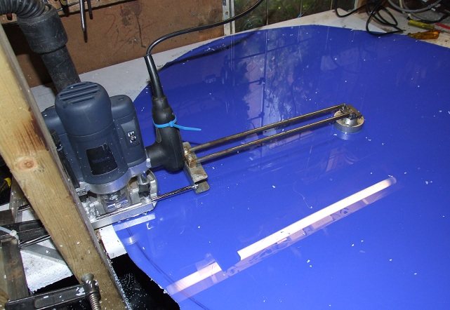
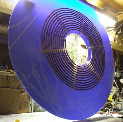
Cutting a 38.5 inch disc using a router
This Acrylic sheet acts as a guard against streamer strikes, and also supports the primary on its underside. To cut the disc I first cut a 2 inch centre hole with a standard hole cutter. A central boss was then made at 2.125 inch diameter, but with a step in the lower 0.25 inch of height that was just under 2 inches.
The boss then sits in the disc's hole lightly clamping it down to stop it lifting, but at the same time allowing rotation of the sheet around the boss.
The router was then clamped to the vertical post on the left hand side, while the anchor point on the right fits into the central boss.
The sheet could then be turned by hand and fed into the router. This method allowed me to cut a very clean edge to the disc.
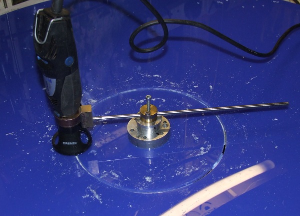
The inner 9 inch circle was next cut using a Dremel.
The extension arm was made to fit into the same boss that the router had used to cut the outer edge, thus ensuring two concentric circles.
This time though the sheet stayed still and the Dremel was turned.
The hole measures 9 inches diameter as the current secondary is 8 inches diameter.
The primary coil itself mounted on what will be the underside of the protection cover for the primary.
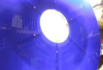
Held against the light, you can see the primary mounted on the underside.
Coupling Adjustment
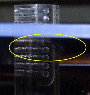
The four posts that support the combined primary coil and its protection cover, each have 9 identically placed holes at their tops.A pin is then simply inserted into the same hole on each post, allowing the position of the primary coil to be easily raised or lowered and thus alter the coupling.
This arrangement gives me a range for the coupling factor (k) from 0.125 to 0.16
My present coupling factor that the coil normally uses is 0.13 against a recommended ratio from JavaTc of 0.141.
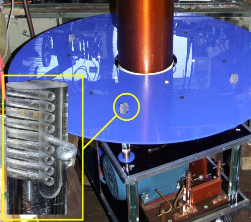
The pin sits underneath the top cover and can just be seen circled in yellow in the photo below.
The pin sits underneath the top cover and can just be seen circled in yellow in the photo below.
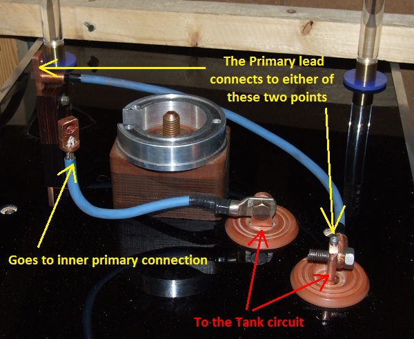
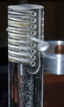
To avoid having too long a tapping lead, I have opted to have two connections underneath, either of which can be used for a shorter primary lead.
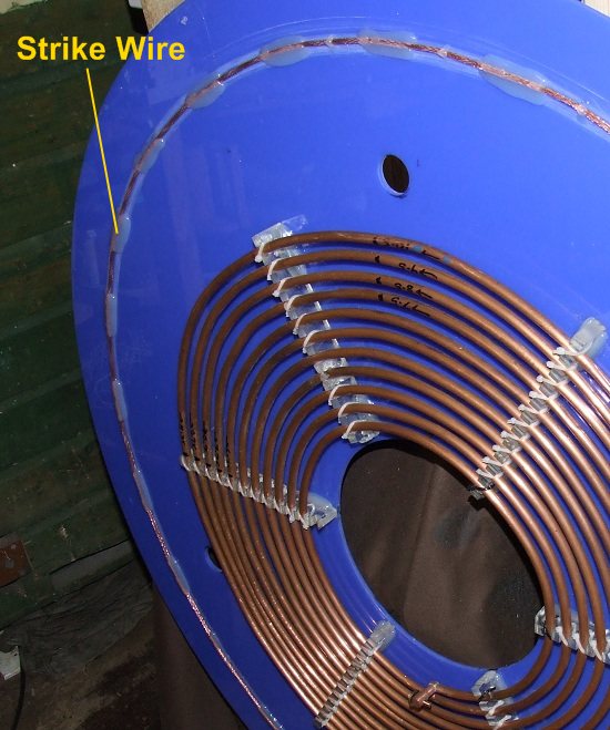
The Strike Wire
(Viewed from the underside)
This circumferential wire acts the same as a strike ring, but is located on the underside of the primary shield. If a streamer should start to go under the shield, this earthed wire will act as a diversion.
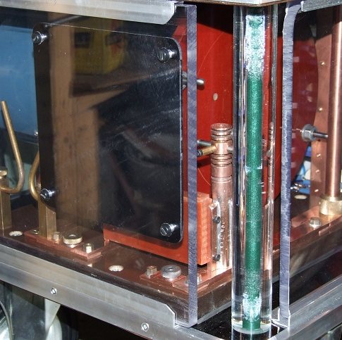
The SRSG's Safety Window
The two 0.5 inch thick pieces of Lexan will provide some containment to any flying pieces of Tungsten in the unlikely event that an electrode collision should occur.
The square of black acrylic serves to blank out the glare from the SRSG, and is bolted on the inside of the Lexan protection window.

The Finished Coil 2015